Inductive position sensor with a cursor and a coupling scale

a cursor and inductive position technology, applied in the field of inductive position sensors, can solve the problems of sensor insensitive to magnetic fields influencing the part of the scale, and achieve the effect of simple alignment of the cursor along the scale and improved accuracy

Active Publication Date: 2006-03-21
MEYER GMBH
View PDF7 Cites 32 Cited by
  • Summary
  • Abstract
  • Description
  • Claims
  • Application Information

AI Technical Summary

Benefits of technology

[0007]These characteristics allow a sensor to be far less sensitive to changes in scale-to-cursor gap, by eliminating detrimental direct coupling between cursor conductors while maintaining coupling via the scale at one half of their maximum possible level. The separate groups of N conductors allow activating N configurations, identical but shifted by T / N, of at least one inducing and one induced conductor. The absence of direct couplings as well as more uniform coupling via the scale, achieved by grouping together the inducing conductors on one hand and the induced ones on the other, makes coupling as a periodic function of the position of the cursor along the scale in said N configurations more uniform, yielding better accuracy, even for comparatively large scale-to-cursor gaps.
[0008]Optimally, the conductors of each one of both cursor groups form meanders or zigzags going back and forth along the measuring path. Direct magnetic coupling between an inducing back-and-forth zigzag and an induced one decreases strongly with their separation, given that each one forms a series of virtually closed inducing or induced loops of alternating polarity, whose opposite effects tend to cancel. Also, as such a back-and-forth zigzag is a closed line, it may be cut anywhere to be connected to the measuring circuit by a pair of very close conductors whose contribution to inductance, hence to coupling, is insignificant. For a given separation between inducing and induced groups, the scale-to-cursor gap may vary more, leading to simpler alignment of the cursor along the scale.

Problems solved by technology

As a result, currents induced in the scale flow across said path rather than along it, making the sensor insensitive to magnetic fields influencing the part of the scale not facing the cursor.

Method used


Image

  • Inductive position sensor with a cursor and a coupling scale
  • Inductive position sensor with a cursor and a coupling scale
  • Inductive position sensor with a cursor and a coupling scale

Examples


Embodiment Construction

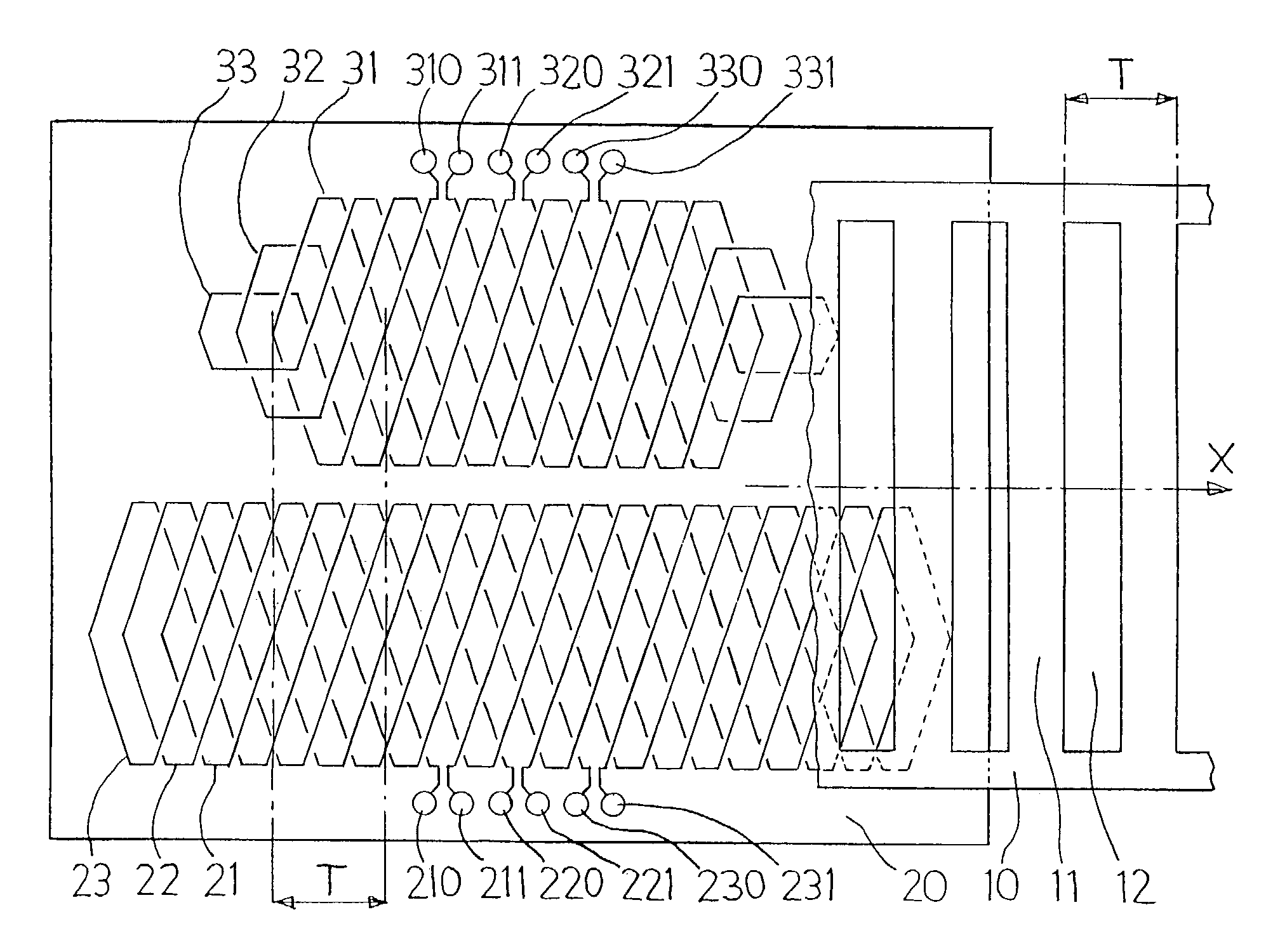
[0022]The scale 10 and the cursor 20 of a sensor according to the invention are shown in FIG. 1; they are relatively movable along a measuring path x, here a straight one. The surface of the cursor 20 facing the scale is shown, as well as a part only of the scale 10, so the cursor stays visible. The planes of the surfaces of the scale 10 and of the cursor 20 facing each other are parallel to the plane of the figure.

[0023]The scale 10 is a conductive ribbon in the shape of a ladder whose rungs 11 are spaced out by a pitch T, forming a series of conductive loops also spaced out by T. Each conductive loop circles around an opening 12 between two rungs 11.

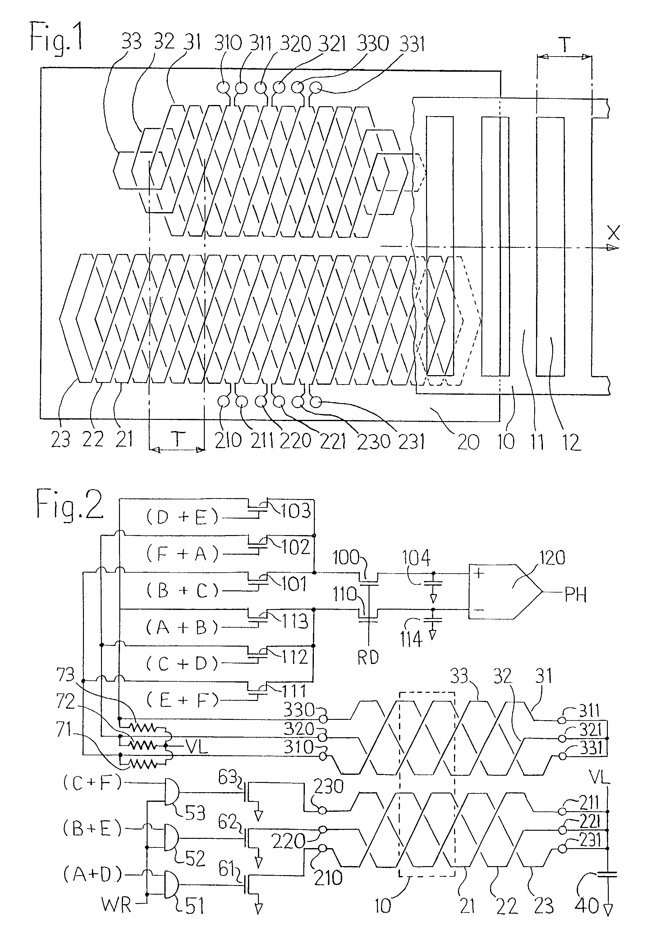
[0024]The cursor 20 has two groups of N=3 interlaced conductors, each conductor forming a zigzag of spatial period 2T whose successive hairpin turns are thus spaced out by the pitch T along the path. The inducing conductors 21, 22, 23 constitute one group, and the induced conductors 31, 32, 33 constitute the other group. These two grou...


PUM


Abstract

The inductive position sensor includes a scale (10) with a series of conductive loops spaced out by a pitch T and a cursor (20) provided with conductors forming each a series of alternating hairpin turns spaced out by a pitch T, the inducing (21 to 23; 42, 44) and induced (31 to 33; 41, 43) cursor conductors are laid out in two separate interlaced conductor groups, coupling between inducing and induced conductors of the second group taking place only via the scale loops. Such a sensor is simple, robust, accurate, insensitive to external electromagnetic fields and tolerant of misalignment between cursor and scale.

Description

FIELD OF THE INVENTION[0001]The invention is an inductive position sensor including a scale and a cursor movable relatively to each other along a measuring path, the scale including one or several conductors forming a series of conductive loops spaced along the measuring path by a pitch T, the cursor including inducing and induced conductors, connected to an electronic measuring circuit and each forming a series of alternating hairpin turns spaced along the measuring path by a pitch T.BACKGROUND OF THE INVENTION[0002]U.S. Pat. No. 5,804,963 discloses an inductive position sensor including the above-described features. The position of the cursor relative to the scale along the path is derived from the measurement of the coupling between inducing and induced cursor conductors via the scale conductors. The magnetic fields generated and picked up by the cursor and scale conductors of such a sensor have a polarity reversal every pitch T along the measuring path. This sensor is insensitiv...

Claims


Application Information

Patent Timeline
Patent Type & Authority Patents(United States)
IPC IPC(8): G01B7/14G01B7/30G01D5/20
CPCG01D5/2053
Inventor MEYER, HANS ULRICH
Owner MEYER GMBH
Why Eureka
Try Eureka