CMOS voltage-controlled oscillator (VCO) with a current-adaptive resistor for improved linearity

a voltage-controlled oscillator and current-adaptive resistor technology, applied in the direction of oscillator, pulse generation by logic circuit, pulse technique, etc., can solve the problems of limited vco bandwidth and insufficient consideration of linear control curren

Inactive Publication Date: 2006-03-21
DIODES INC
View PDF9 Cites 21 Cited by
  • Summary
  • Abstract
  • Description
  • Claims
  • Application Information

AI Technical Summary

Problems solved by technology

However, this linear control current does not take into account a non-linear current-to-frequency response of the second po

Method used


Image

  • CMOS voltage-controlled oscillator (VCO) with a current-adaptive resistor for improved linearity
  • CMOS voltage-controlled oscillator (VCO) with a current-adaptive resistor for improved linearity
  • CMOS voltage-controlled oscillator (VCO) with a current-adaptive resistor for improved linearity

Examples


Embodiment Construction

[0015]The present invention relates to an improvement in voltage-controlled oscillators (VCOs). The following description is presented to enable one of ordinary skill in the art to make and use the invention as provided in the context of a particular application and its requirements. Various modifications to the preferred embodiment will be apparent to those with skill in the art, and the general principles defined herein may be applied to other embodiments. Therefore, the present invention is not intended to be limited to the particular embodiments shown and described, but is to be accorded the widest scope consistent with the principles and novel features herein disclosed.

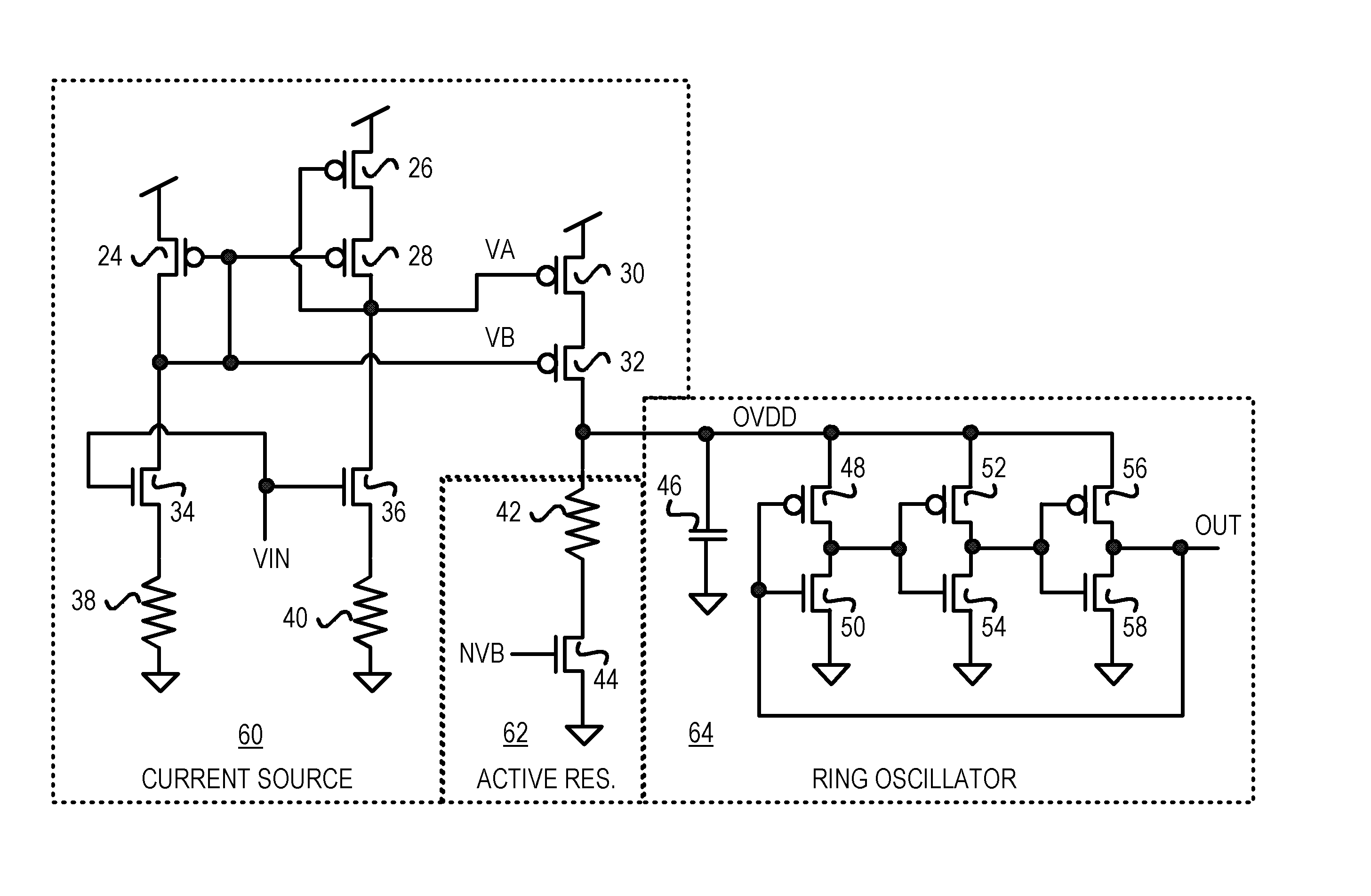
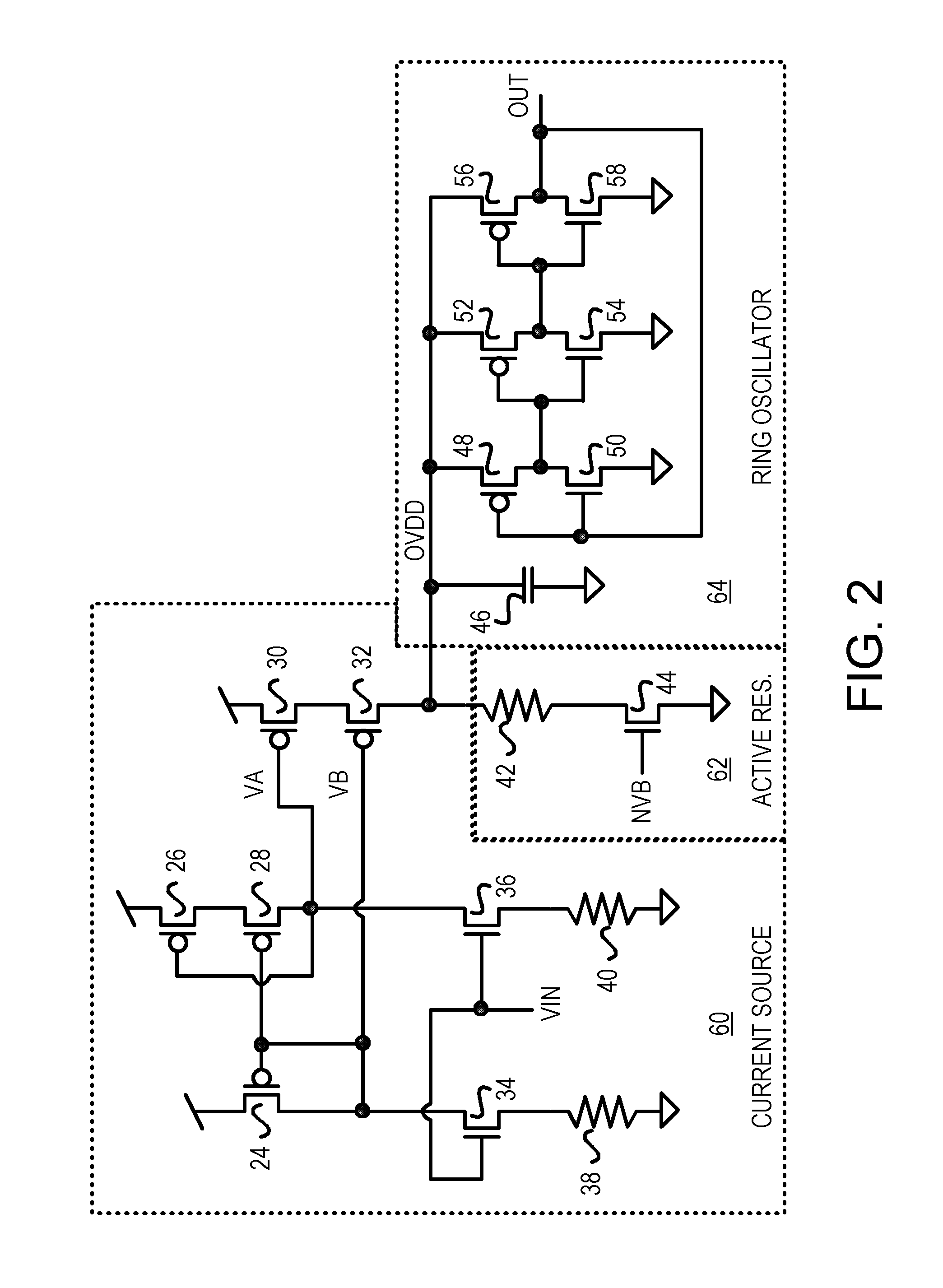
[0016]FIG. 2 is a schematic diagram of a VCO with a current-adaptive resistor. Current source 60 receives the loop-filter voltage VIN which adjusts as a charge pump charges and discharges a loop filter capacitor in a PLL. The current delivered to the oscillator power-supply OVDD varies with VIN. A higher VIN prod...


PUM


Abstract

A voltage-controlled oscillator (VCO) for a phase-locked loop (PLL) has improved bandwidth and performance at lower frequency. A variable current source supplies a current to an internal oscillator-power node. The current varies with the VCO input voltage. The internal oscillator-power node drives the sources of p-channel transistors in inverter stages in the ring oscillator. The variable current causes the internal oscillator-power node's voltage to vary, which varies the output frequency. An active resistor is in parallel with the ring oscillator. The active resistor has a resistor and an n-channel transistor in series between the oscillator-power node and ground. The n-channel transistor has a fixed bias voltage on its gate and is non-linear. The non-linear effective resistance of the n-channel transistor improves overall linearity of the ring oscillator. The parallel effective resistance of the active resistor lowers overall effective resistance of the ring oscillator. Oscillator bandwidth at lower frequencies improves.

Description

BACKGROUND OF INVENTION[0001]This invention relates to voltage-controlled oscillators (VCOs), and more particularly for VCO with a current-adaptive resistor.[0002]Precise clocks are useful in many electronic systems. Clock generator circuits can be adjustable, such as by using a voltage-controlled oscillator (VCO). The frequency of the generated clock can be adjusted by adjusting the voltage that is input to the VCO. Oftentimes the VCO is part of a phase-locked loop (PLL).[0003]FIG. 1 shows a prior-art PLL. A reference clock and a feedback clock are applied to phase detector 10, which compares the edges of the 2 clocks and generates UP and DOWN signals to charge pump 12. Charge pump 12 responds by charging or discharging a loop filter that includes capacitor 22 and resistor 20. The voltage across the loop filter changes, altering the voltage input to VCO 14. VCO 14 oscillates at a frequency determined by the input voltage from the loop filter.[0004]Clock driver 16 buffers the output...

Claims


Application Information

Patent Timeline
IPC IPC(8): H03B5/04H03B5/24
CPCH03K5/133H03L7/0995H03K2005/00032H03L7/18H03L7/0891
Inventor GUO, ZHANGQIZHANG, MICHAEL Y.
Owner DIODES INC
Why Eureka
Try Eureka