Distributed monitoring for a video security system

a technology for video security and distribution monitoring, applied in the field of distribution monitoring for video security systems, can solve problems such as false alarms, owner of the system being subject to significant fines, and false alarms wasting the limited resources available to the authorities to respond to legitimate alarm situations

Inactive Publication Date: 2006-03-21
COMCAST CABLE COMM LLC
View PDF103 Cites 430 Cited by
  • Summary
  • Abstract
  • Description
  • Claims
  • Application Information

AI Technical Summary

Problems solved by technology

Inherent in security systems is the problem of false alarms.
In situations where local authorities are notified of alarms, false alarms can result in the owner of the system being subject to significant fines.
In addition, false alarms waste the limited resources available to the authorities to respond to legitimate alarm situations.
However, the occurrence of an alarm provides no indication as to its cause.
Thus, the operator has no other knowledge by which he can determine if an alarm signals the presence of a real intruder, or if it is a false alarm.
Regardless of why they occur, all false and unwanted alarms detrimentally affect the efficiency and operation of a security system.
However, in prior art devices these images have been low-resolution, freeze-frame pictures, making it difficult for a viewer to discern what is being shown.
In addition, in many prior art devices, the video images may not be received by the monitoring party until several moments have passed after the recorded event has actually taken place likely causing any response to be late and less effective.
An additional problem with some existing security systems is that once a person has left the property, it is common for that person to worry that he or she has forgotten to activate or arm the security system.

Method used


Image

  • Distributed monitoring for a video security system
  • Distributed monitoring for a video security system
  • Distributed monitoring for a video security system

Examples


Embodiment Construction

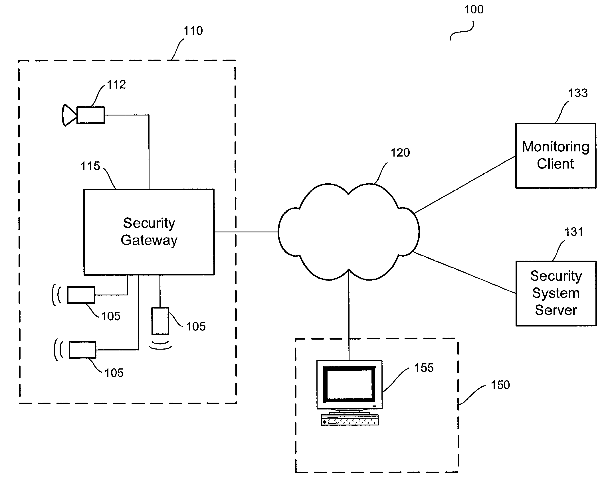
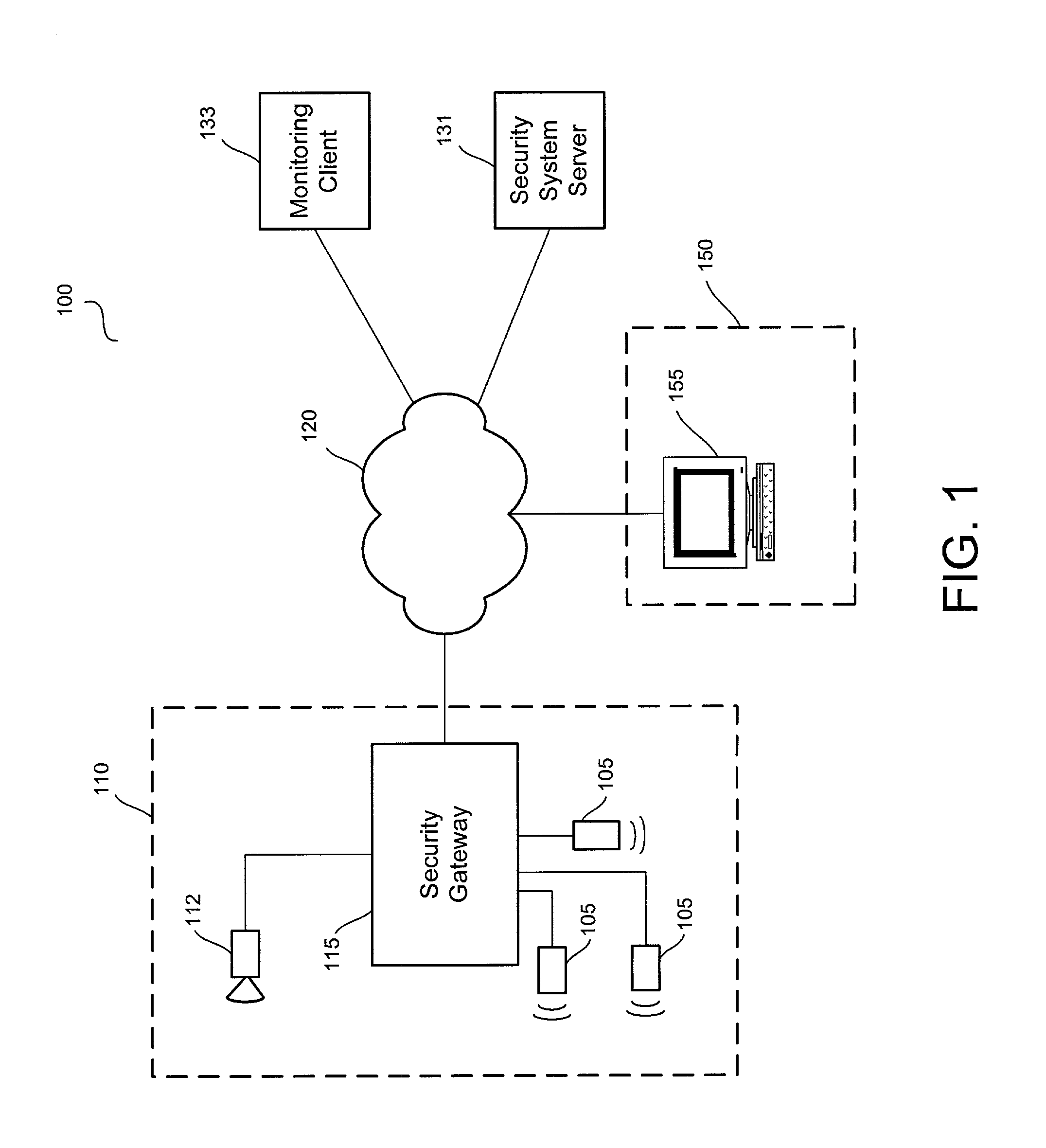
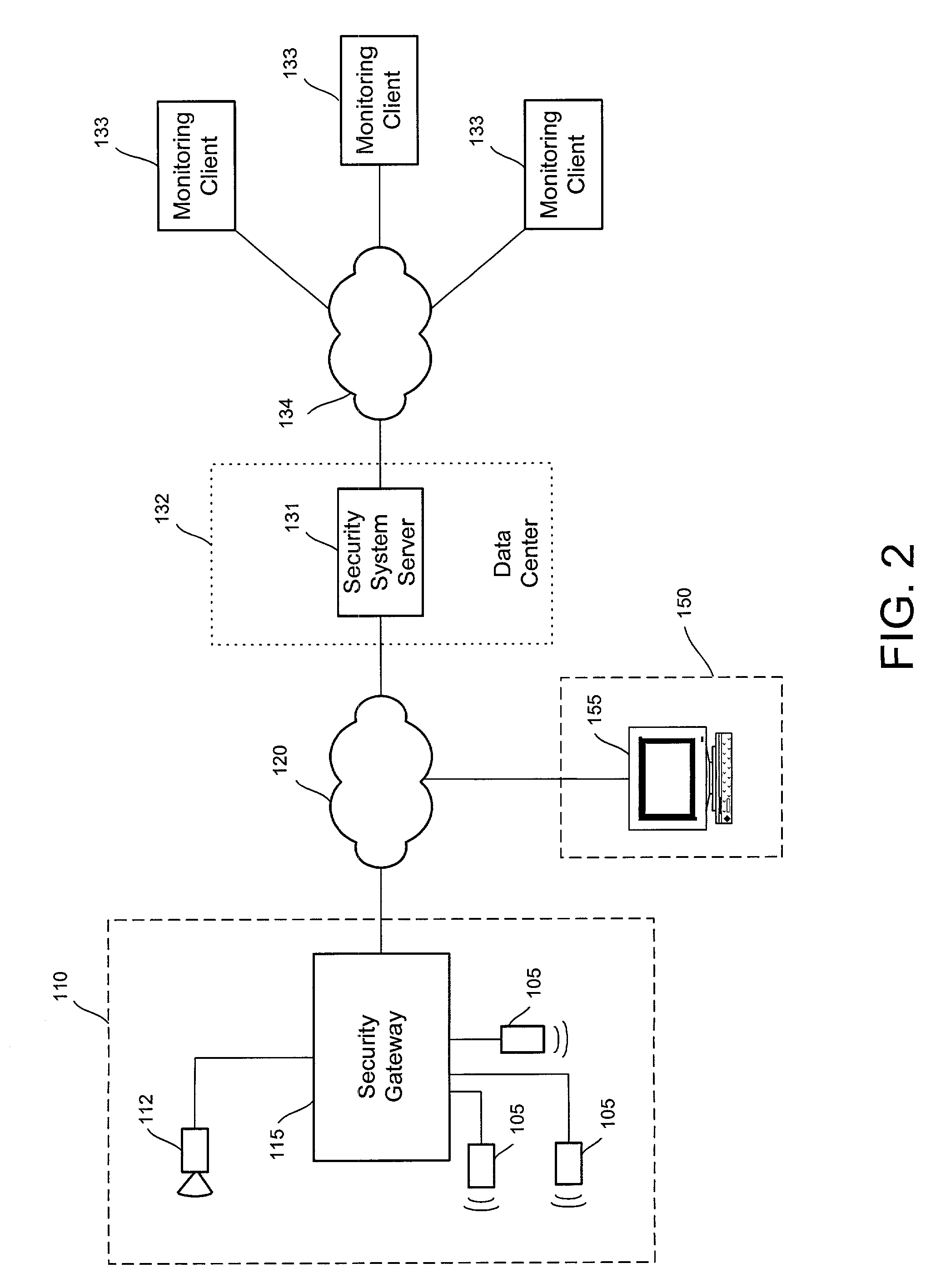
[0026]The present invention addresses several shortcomings of the prior art with a security system and framework that is configured to deliver real-time information, including video and / or about alarm conditions to monitoring personnel for them to verify alarm conditions and take appropriate follow up action. As a further advantage, the framework may be easily adapted for use in other applications that incorporate real-time information and video delivery.

[0027]The term “security system” is used broadly to mean a system for monitoring a premises, e.g. for the purpose of discouraging and responding to burglaries, fires, and other emergency situations. Such a security system is suited for residential homes, but may also find use with schools, nursing homes, hospitals, businesses or any other location in which real-time information may be useful in obtaining adequate response upon the occurrence of alarm conditions. By integrating broadband features, including audio and video capabiliti...


PUM


Abstract

A system and method for distributed monitoring and remote verification of conditions surrounding an alarm condition in a security system. A security gateway detects alarm conditions at a premises and records video relating to the alarm condition. The security gateway transmits an alarm notification and the video across a network to a security system server in substantially real time. The security system server relays information to one or more distributed monitoring clients using rules-based routines for verification of the alarm condition. An operator at a monitoring client determines whether the alarm condition represents an actual alarm event and activates an appropriate response.

Description

RELATED APPLICATIONS[0001]The present application is a continuation-in-part of U.S. application Ser. No. 09 / 954,976, filed Sep. 18, 2001, titled “Video Security System”. Separate from the foregoing, U.S. patent application No. 09 / 954,976 is a continuation-in-part of U.S. application Ser. No. 09 / 357,196, filed Jul. 20, 1999, now U.S. Pat. No. 6,690,411.BACKGROUND OF THE INVENTION[0002]1. Field of the Invention[0003]The present invention relates generally to a security system. More specifically, this invention relates to a device and method for the remote verification and monitoring of conditions surrounding an alarm signal.[0004]2. Description of Related Art[0005]Inherent in security systems is the problem of false alarms. In situations where local authorities are notified of alarms, false alarms can result in the owner of the system being subject to significant fines. In addition, false alarms waste the limited resources available to the authorities to respond to legitimate alarm si...

Claims


Application Information

Patent Timeline
Patent Type & Authority Patents(United States)
IPC IPC(8): G08B1/00G08B13/196G08B15/00H04N7/18
CPCG08B13/19656G08B13/19669H04N7/181G08B13/19691G08B13/1968
Inventor NAIDOO, SURENDRA N.GLASGOW, WILLIAM P.FELDKAMP, GREGORY E.
Owner COMCAST CABLE COMM LLC
Why Eureka
Try Eureka