
Mapping of control information to control channel elements

a control information and channel element technology, applied in the field of mapping of control information to control channel elements, can solve the problems of inability to use, inability to extend the transmission bandwidth, and loss of all resource assignments contained therein, and achieve the effect of expanding the overall system bandwidth and widening the transmission bandwidth

Active Publication Date: 2013-08-29
SUN PATENT TRUST
View PDF4 Cites 120 Cited by
  • Summary
  • Abstract
  • Description
  • Claims
  • Application Information

AI Technical Summary

Benefits of technology

The invention suggests a way to efficiently allocate control information in a communication system. It proposes a method to map the control information to specific regions within a sub-frame of an OFDM-based system. This allows for distributed and localized mapping of control information, while minimizing the allocation of resources to user equipment. Additionally, the invention allows for mapping of control channel elements in multiple physical resource block pairs, which can be located close to each other or distributed throughout the frequency domain. This approach optimizes the use of available system resources and ensures efficient allocation of control information.

Problems solved by technology

If the user equipment is unable to decode the PCFICH or obtains an erroneous PCFICH value, this PCFICH detection error will result in the user equipment not being able to correctly decode the L1 / L2 control signaling (PDCCHs) comprised in the control signaling region, so that all resource assignments contained therein are lost.
Assuming a simple and cost-effective receiver at the relay node, partially invisible OFDM symbols cannot be used since they would contain a lot of interference and should therefore be considered as corrupt.
If the eNodeB-to-relay node link operates in the same frequency spectrum as the relay node-to-UE link, simultaneous eNodeB-to-relay node and relay node-to-UE transmissions on the same frequency resource may not be feasible due to the relay transmitter causing interference to its own receiver, unless sufficient isolation of the outgoing and incoming signals is provided.

Method used


Image

  • Mapping of control information to control channel elements
  • Mapping of control information to control channel elements
  • Mapping of control information to control channel elements

Examples


Embodiment Construction

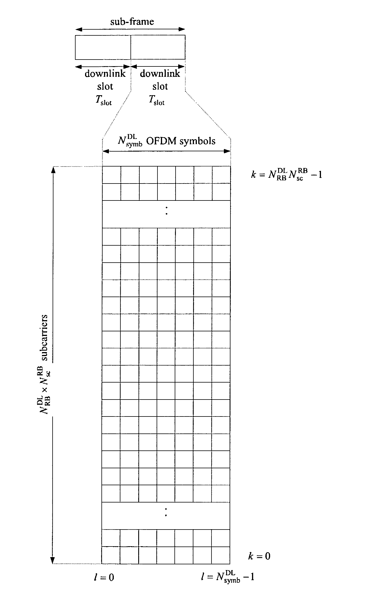
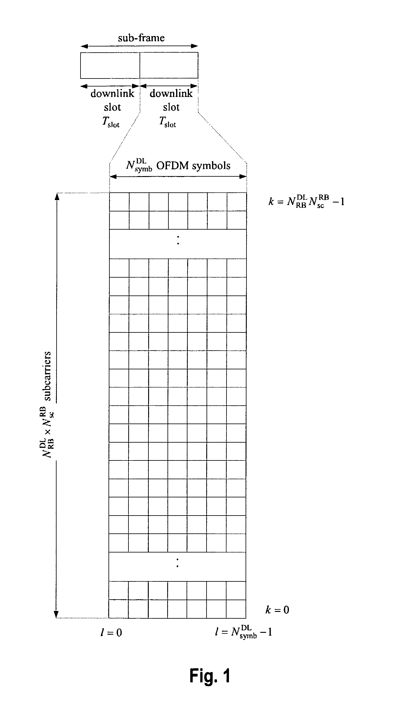
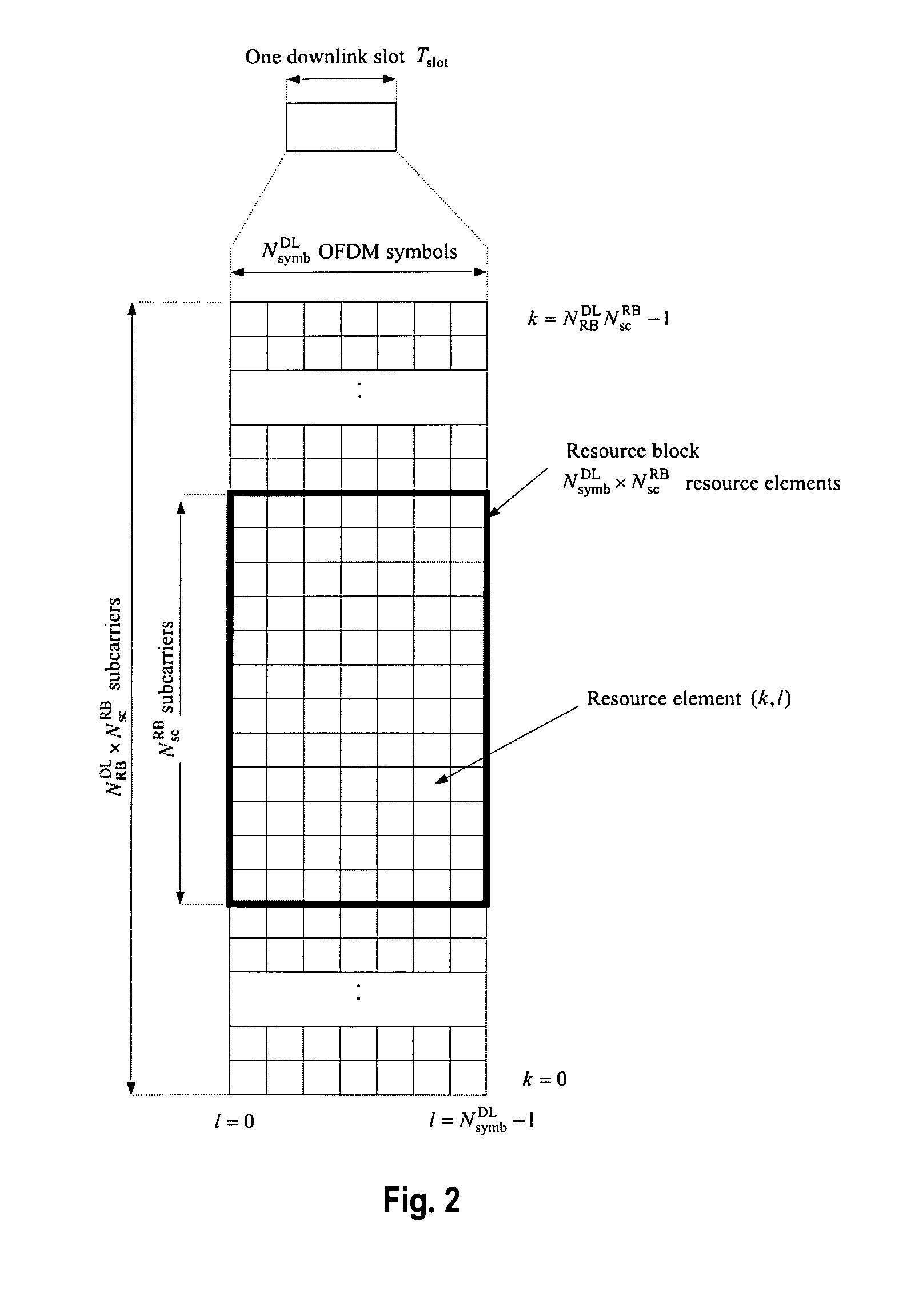
[0147]The following paragraphs will describe various embodiments of the invention. For exemplary purposes only, most of the embodiments are outlined in relation to an orthogonal single-carrier uplink radio access scheme according to 3GPP LTE (Release 8) and LTE-A (Release 10) mobile communication systems discussed in the Technical Background section above. It should be noted that the invention may be advantageously used for example in connection with a mobile communication system such as 3GPP LTE (Release 8) and LTE-A (Release 10) communication systems previously described, but the invention is not limited to its use in this particular exemplary communication network.

[0148]The explanations given in the Technical Background section above are intended to better understand the mostly 3GPP LTE (Release 8) and LTE-A (Release 10) specific exemplary embodiments described herein and should not be understood as limiting the invention to the described specific implementations of processes and...


PUM


Abstract

The invention relates to a new structure of a control channel region within a sub-frame of a 3GPP-based based communication system using OFDM in the downlink. This new structure of a control channel region is inter alia particularly suitable for conveying physical downlink control channel information from a donor eNodeB to a relay node. The control channel region is divided in CCEs that have equal size irrespective of the presence of further cell-specific and / or UE-specific reference signals within the control channel region. This is achieved by dividing the control channel region in plural sub-CCEs that are combined to CCEs all having equal size (in terms of resource elements that can be used for the signaling of control information). The control channel region is divided in the frequency domain and / or time domain in a FDM respectively TDM fashion in order to obtain the sub-CCEs

Description

FIELD OF THE INVENTION[0001]The invention relates to a new structure of a control channel region within a sub-frame of a 3GPP-based based communication system using OFDM in the downlink. This new structure of a control channel region is inter alia particularly suitable for conveying physical downlink control channel information from a donor eNodeB to a relay node. However, the new structure of a control channel region within a sub-frame may also be used on the air interface between eNodeBs and user equipments as well as the air interface between the eNodeBs and relay nodes.[0002]The invention further provides a method for mapping physical downlink control channel information for a receiving apparatus to control channel elements of a control channel region of a sub-frame of a 3GPP-based based communication system using OFDM in the downlink and to a method for receiving control information for a receiving apparatus of a 3GPP-based communication system using OFDM in the downlink. Moreo...

Claims


Application Information

Patent Timeline
Patent Type & Authority Applications(United States)
IPC IPC(8): H04W72/04
CPCH04L5/0007H04L5/001H04W72/042H04L5/0048H04L5/0053H04L5/0023H04W72/23H04W72/0446
Inventor FENG, SUJUANGOLITSCHEK EDLER VON ELBWART, ALEXANDERWENGERTER, CHRISTIAN
Owner SUN PATENT TRUST
Learn More