Optical network subscriber access architecture

a subscriber access and optical network technology, applied in multiplex communication, transmission, electrical equipment, etc., can solve the problems of limited subscriber coverage, dsl access is also limited by twisted pair copper line integrity, and dsl is not available to many phone company subscribers

Inactive Publication Date: 2007-01-30
RPX CLEARINGHOUSE
View PDF7 Cites 124 Cited by
  • Summary
  • Abstract
  • Description
  • Claims
  • Application Information

AI Technical Summary

Benefits of technology

[0013]The dual switch fabrics may include a first switch fabric module and a second switch fabric module. Each switch fabric module may be coupled to one or both of the d

Problems solved by technology

The phone companies have achieved reasonable penetration and higher bandwidth than cable modems, although the technology is distance limited resulting in limited subscriber coverage.
In addition, access to DSL is also limited by twisted pair copper line integrity.
Thus, DSL is not available to many phone company subscribers.
However, cable modem technology utilizes a shared medium, and, thus, has security and bandwidth limitations.
High penetration rates r

Method used


Image

  • Optical network subscriber access architecture
  • Optical network subscriber access architecture
  • Optical network subscriber access architecture

Examples


Embodiment Construction

)

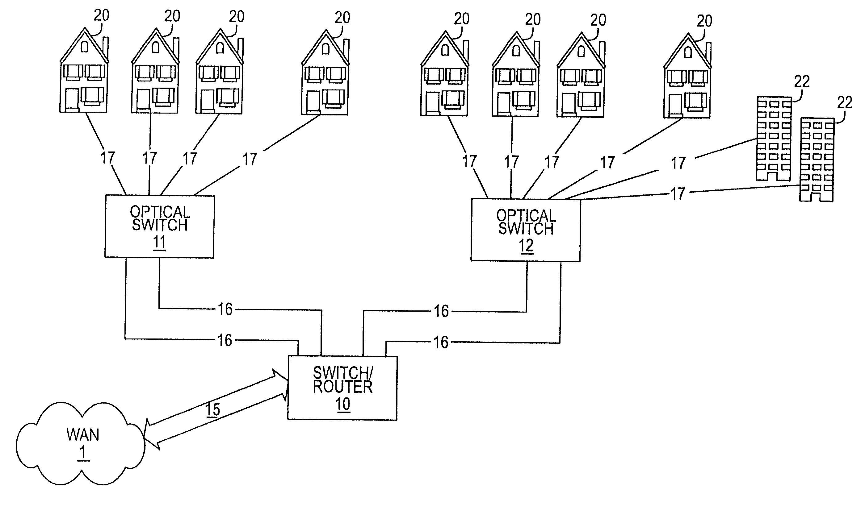
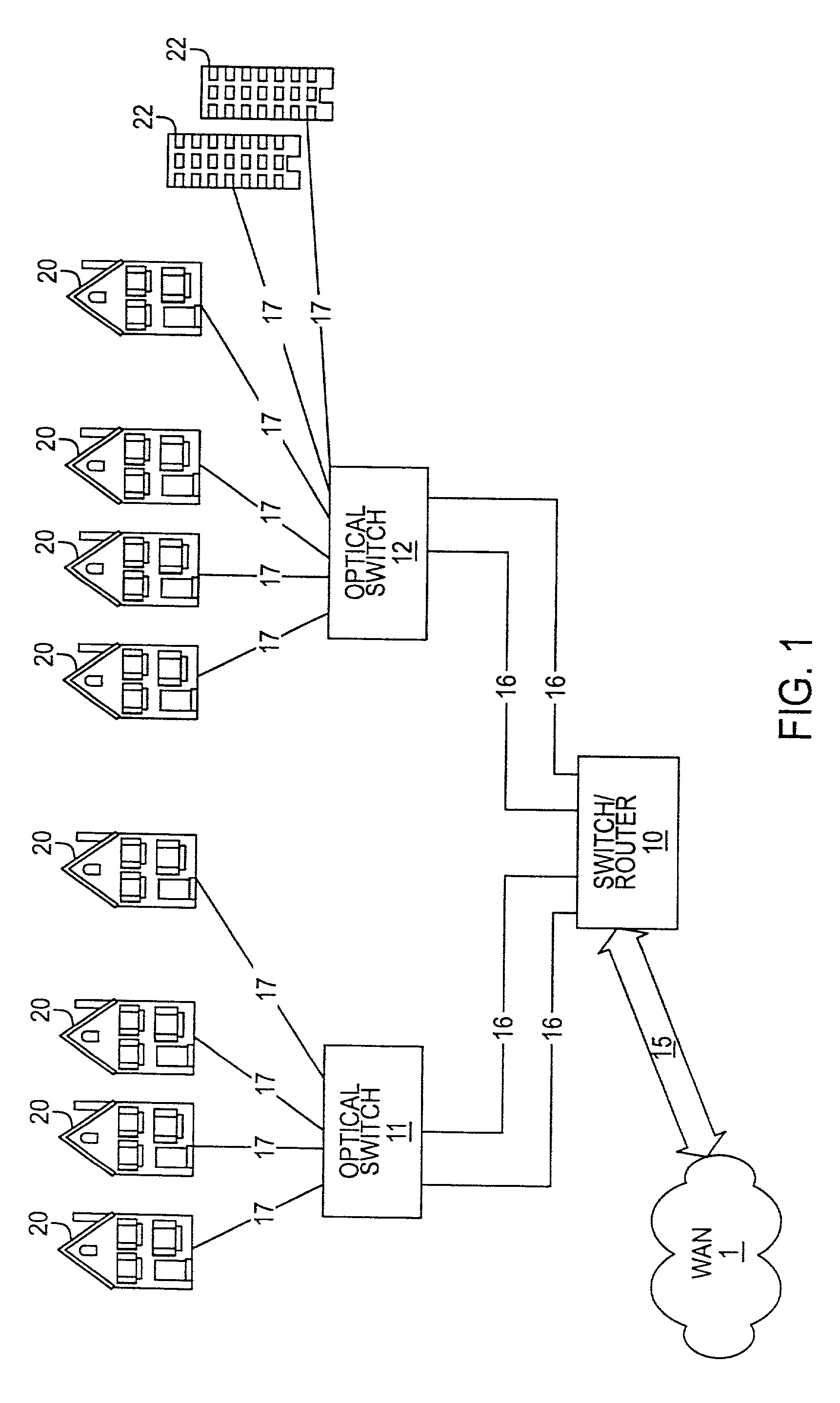
[0023]Referring to FIG. 1, there is shown a block diagram illustrating one embodiment of an optical network according to one embodiment of this invention. Optical network 100 may include a network 1, a switch router 10, modular switches 11, 12, houses 20 and buildings 22.

[0024]In one embodiment, network 1 may include a wide area network or any other appropriate network. Network 1 may be, include or interface to any one or more of, for instance, the Internet, an intranet, a PAN (Personal Area Network), a LAN (Local Area Network), a WAN (Wide Area Network) or a MAN (Metropolitan Area Network), a storage area network (SAN), a frame relay connection, an Advanced Intelligent Network (AIN) connection, a synchronous optical network (SONET) connection, a digital T1, T3, E1 or E3 line, Digital Data Service (DDS) connection, DSL (Digital Subscriber Line) connection, an Ethernet connection, an ISDN (Integrated Services Digital Network) line, a dial-up port such as a V.90, V.34 or V.34bis anal...


PUM


Abstract

A technique for providing an optical signal to a destination. In one embodiment, the technique is realized through the use of an environmentally hardened, modular switch and a fiber distribution methodology. The modular switch may include fiber access ports, power access ports, dual power supply modules, dual switch fabric modules, dual optical trunking modules, and multiple subscriber service modules that house subscriber service ports and serve a total of up to 96 end points. The dual optical trunking modules may act as an interface between an optical network and the dual switch fabrics, and provide redundancy and variable optical transmission distance between the modular switch and the optical network to which the modular switch is connected. The dual switch fabrics are used for switching and aggregating signals and providing redundancy. Each subscriber service module acts as an interface between one or more subscriber end points and the dual switch fabrics of the modular switch. The subscriber service modules may be coupled to one or both of the dual switch fabrics and a total of up to 96 subscriber end points. Subscriber end point connectivity may be achieved via subscriber service ports (housed within a subscriber service module), one or more of the fiber access ports, external fiber optic splice cabinet, fiber optic trunk cable, and one or more fiber breakout points (housed by pedestals). The subscriber end points may consist of one or more optical or electrical subscriber connection types.

Description

CROSS-REFERENCE TO RELATED APPLICATIONS[0001]This patent application is related to the subject matter of copending U.S. Patent Application No. 60 / 247,054, filed Nov. 13, 2000, which is hereby incorporated by reference herein in its entirety.FIELD OF THE INVENTION[0002]The present invention relates generally to an optical access network architecture and, more particularly, to a technique for using optical fibers to provide multi-service network access to homes, businesses, and or multi-dwelling units.BACKGROUND OF THE INVENTION[0003]As the demand for Internet use grows, the need for high speed internet access is also growing. Deregulation has allowed different service providers to compete for voice, video and data subscribers. Cable TV companies have installed fiber optics and upgraded their networks to become a leader in the area of high speed Internet access service.[0004]Phone companies are deploying DSL technology to enable higher bandwidth Internet connectivity over traditional ...

Claims


Application Information

Patent Timeline
IPC IPC(8): H04J14/00
CPCH04L45/22H04L45/28H04Q11/0067H04Q2011/0081H04Q11/0005
Inventor SKARICA, CHRISTOPHER M.PRATT, BARRY C. E.DANIELI, OSCARPROVAN, NORMAN G.
Owner RPX CLEARINGHOUSE
Why Eureka
Try Eureka