Radio communication system

a radio communication and system technology, applied in the field of radio communication systems, can solve the problems of affecting the quality of optical signals, the inability to separate signals to be received and noise from each other, and the inability to prevent optical signal deterioration, so as to prevent the quality deterioration of optical signals

Inactive Publication Date: 2005-12-01
PANASONIC CORP
View PDF2 Cites 112 Cited by
  • Summary
  • Abstract
  • Description
  • Claims
  • Application Information

AI Technical Summary

Benefits of technology

[0122] Preferably, all the optical connectors for connecting optical transmission paths are obliquely polished connectors. Thus, unlike the case where other connectors are used, light reflect

Problems solved by technology

In the case where the level of a wireless signal received by the relay apparatus is too high, when the wireless signal is converted into an optical signal, the optical signal is distorted.
By contrast, in the case where the level of a wireless signal received by the relay apparatus is too low, the wireless signal to be received and noise cannot be separated from each other.
Out-band frequency components have adverse effects on other communication devices which communicate using the same frequency band as that of the out-band frequency components, electric devices existing in the vicinity of the wireless communication terminal, and the like.
The reason is that when the D/U ratio is too low, the relay apparatus cannot separate the signal to be received and noise from each other.
This complicates the structure of the system.
Even in the case where a signal is transmitted to a control apparatus using a frequency-division multiplexing system also, there is a problem that the structure of the system is complicated.
This complicates the structure of the relay apparatus and makes it difficult to reduce the size of the relay apparatus.
As a result, there is a problem that the system having such a structure is expensive.
As described above, the conventional wireless communication system described in the specification of Japanese Patent No. 2885143, although being capable of fulfilling t

Method used


Image

  • Radio communication system
  • Radio communication system
  • Radio communication system

Examples


embodiment 1

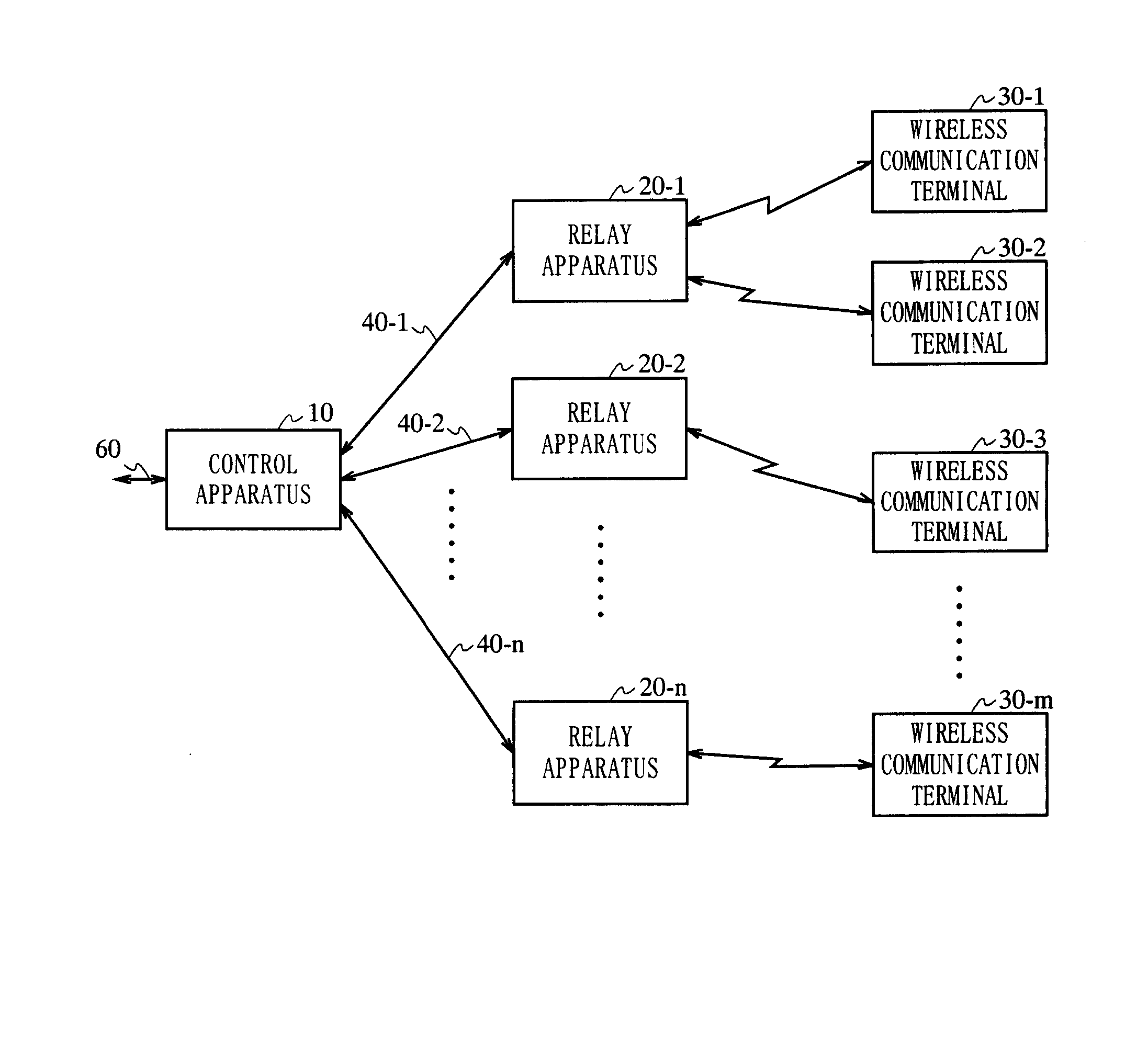
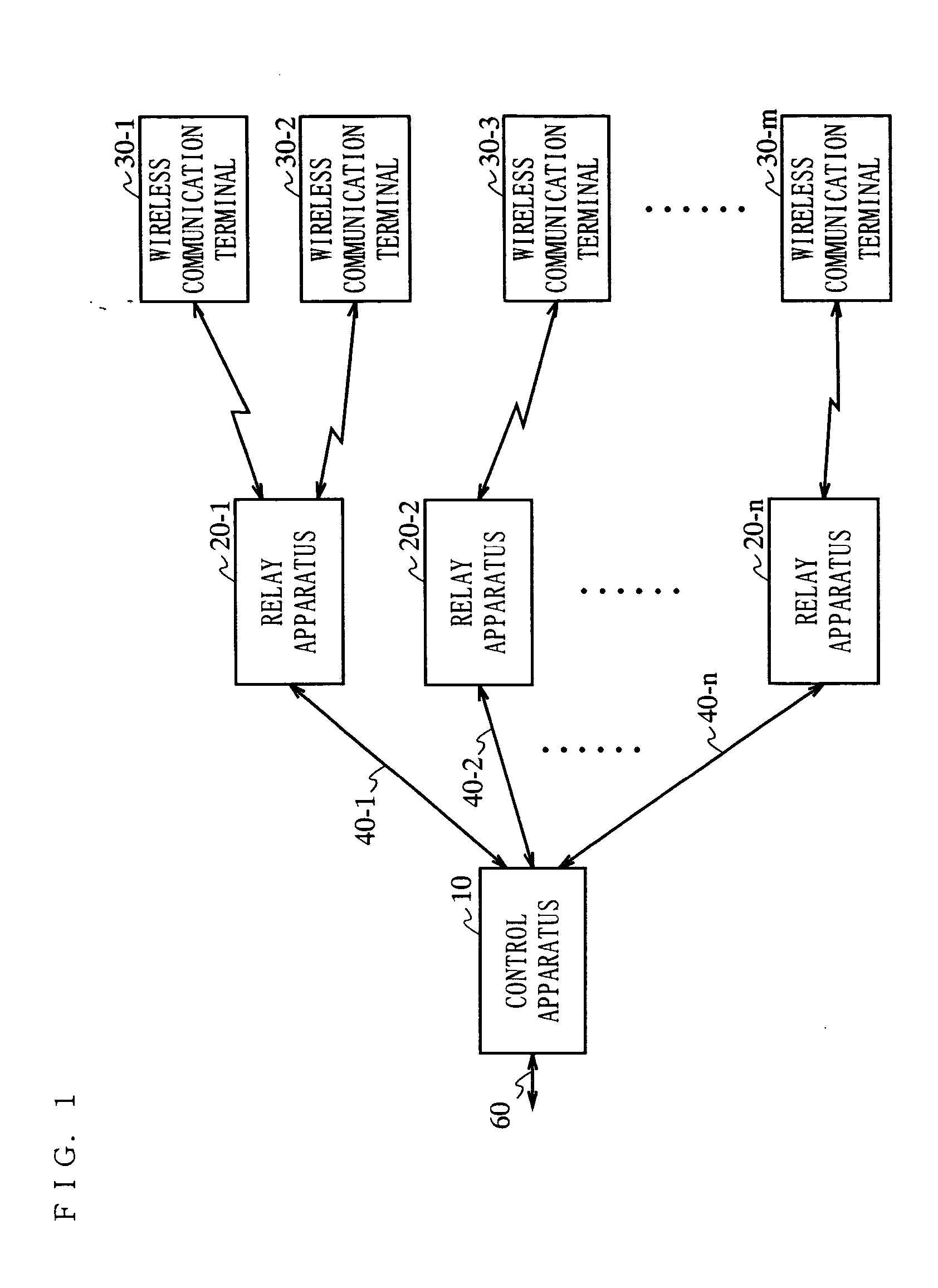
[0171]FIG. 1 is a block diagram showing a structure of a wireless communication system according to Embodiment 1 of the present invention.

[0172] In FIG. 1, the wireless communication system includes a control apparatus 10, relay apparatuses 20-1 through 20-n (n: a natural number of 1 or greater), and wireless communication terminals 30-1 through 30-m. The control apparatus 10 and the relay apparatuses 20-1 through 20-n are connected to each other via optical transmission paths 40-1 through 40-n, respectively. The relay apparatuses 20-1 through 20-n and the wireless communication terminals 30-1 through 30-m are connected to each other wirelessly. The optical transmission paths are, for example, optical fibers.

[0173] The control apparatus 10 and an external network (not shown) are connected to each other via an Ethernet (registered trademark) cable 60. The control apparatus 10 and the external network may be connected to each other via a cable other than the Ethernet (registered tra...

embodiment 2

[0218]FIG. 8 is a block diagram showing a structure of a control apparatus 10b included in a wireless communication system according to Embodiment 2 of the present invention.

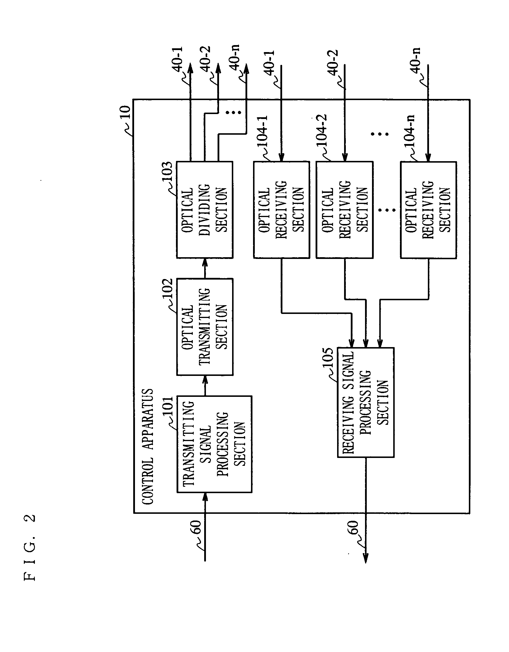
[0219] The control apparatus 10b shown in FIG. 8 is different from the control apparatus 10 shown in FIG. 2 in including a transmitting signal dividing section 107 instead of the optical dividing section 103. The other parts of the structure are substantially the same as those of Embodiment 1, and elements which are substantially the same as those of FIG. 2 bear identical reference numerals thereto and descriptions thereof will be omitted. In this embodiment, the relay apparatus 20 has the structure shown in FIG. 3 except that the level control section 207 is not included.

[0220] In the control apparatus 10b, the transmitting signal processing section 101 modulates a signal transmitted from an external network and outputs the modulated signal to the transmitting signal dividing section 107.

[0221] The transmitt...

embodiment 3

[0263] Hereinafter, a wireless communication system according to Embodiment 3 of the present invention will be described. The wireless communication system according to this embodiment, upon detecting that the quality of an optical signal is deteriorated, stops transmission of the wireless signal from a relay apparatus. When a wireless signal with deteriorated quality is transmitted or received, other communication devices or human body may possibly be adversely influenced. Therefore, when communicating using a wireless signal, the quality of the wireless signal transmitted by a communication device needs to fulfill the public conditions regulated by the Radio Law. In this embodiment, an exemplary case where the wireless communication system evaluates the quality of an optical signal will be described.

[0264]FIG. 14 is a block diagram showing a structure of a relay apparatus 20b included in a wireless communication system according to this embodiment. In FIG. 14, the relay apparatus...


PUM


Abstract

The present invention is directed to a wireless communication system capable of keeping a level of a wireless signal received by a relay apparatus (20) within a predetermined dynamic range. In a control apparatus (10), a transmitting section (102) converts a downstream electric signal into a downstream optical signal and transmits the downstream optical signal to the relay apparatus (20) via an optical transmission path (40). The relay apparatus (20) converts the received downstream optical signal into a downstream electric signal and transmits the downstream electric signal as a wireless signal to a wireless communication terminal (30) from a transmitting/receiving antenna section (204). In the relay apparatus (20), a level adjustment section (207) adjusts the level of the wireless signal transmitted by the relay apparatus (20) such that the receiving level of the wireless signal received by the relay apparatus is kept within a predetermined range.

Description

TECHNICAL FIELD [0001] The present invention relates to a system in which a control apparatus communicates with a wireless communication terminal via a relay apparatus, and more particularly to a system in which the control apparatus and the relay apparatus are connected to each other via an optical transmission path. BACKGROUND ART [0002] Recently, wireless communication systems in which a relay station for communicating with a wireless communication terminal wirelessly is connected to a control apparatus via an optical transmission path have been used (for example, Japanese Laid-Open Patent Publication No. 9-233050). [0003]FIG. 43 is a diagram showing a structure of a conventional wireless communication system described in Japanese Laid-Open Publication No. 9-233050. In the wireless communication system shown in FIG. 43, a control apparatus 19 converts a modulated signal into an optical signal and transmits the optical signal to the relay apparatus 29 via an optical transmission p...

Claims


Application Information

Patent Timeline
IPC IPC(8): H04B7/005H04B10/00H04B10/071H04B10/077H04B10/079H04B10/272H04J13/00H04W52/04H04W52/14H04W52/24H04W88/08H04W92/00
CPCH04B10/25754H04W88/085H04W52/24H04W52/143H04B7/14H04B10/25H04L12/28H04W16/00
Inventor UTSUMI, KUNIAKIYAMAMOTO, HIROAKIMASUDA, KOUICHINIIHO, TSUTOMUNAKASO, MARIKOTANAKA, KAZUOSASAI, HIROYUKI
Owner PANASONIC CORP
Why Eureka
Try Eureka