
Apparatus for reference image rotation, and computer software product and method for reference image rotation

a technology of reference image and computer software, applied in the direction of diagnostic recording/measuring, instruments, applications, etc., can solve the problems of difficult even for experienced users to correctly interpret the actual position of slices using the depicted sectional, and the sign rule for determining the direction of rotation, i.e. positive or negative, is very complicated, and achieves the effect of improving display

Inactive Publication Date: 2006-03-21
SIEMENS HEALTHCARE GMBH
View PDF14 Cites 34 Cited by
  • Summary
  • Abstract
  • Description
  • Claims
  • Application Information

AI Technical Summary

Benefits of technology

[0010]An object of the present invention is to provide an apparatus for representing reference images of patients and slices to be measured in a displayed reference image for assisting the positioning of slices in preparation for a slice-by-slice measurement, and a corresponding computer software product for an apparatus of this type, which enable a user to position slices to be measured in a displayed reference image by means of an improved display in a simple manner.
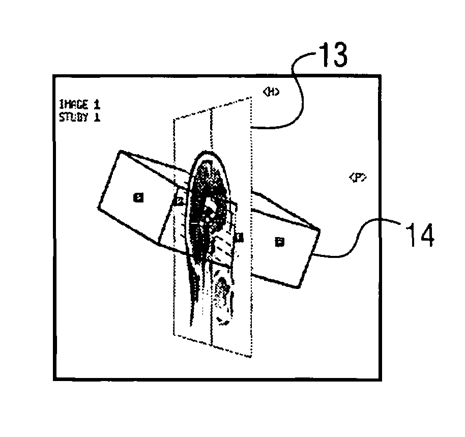
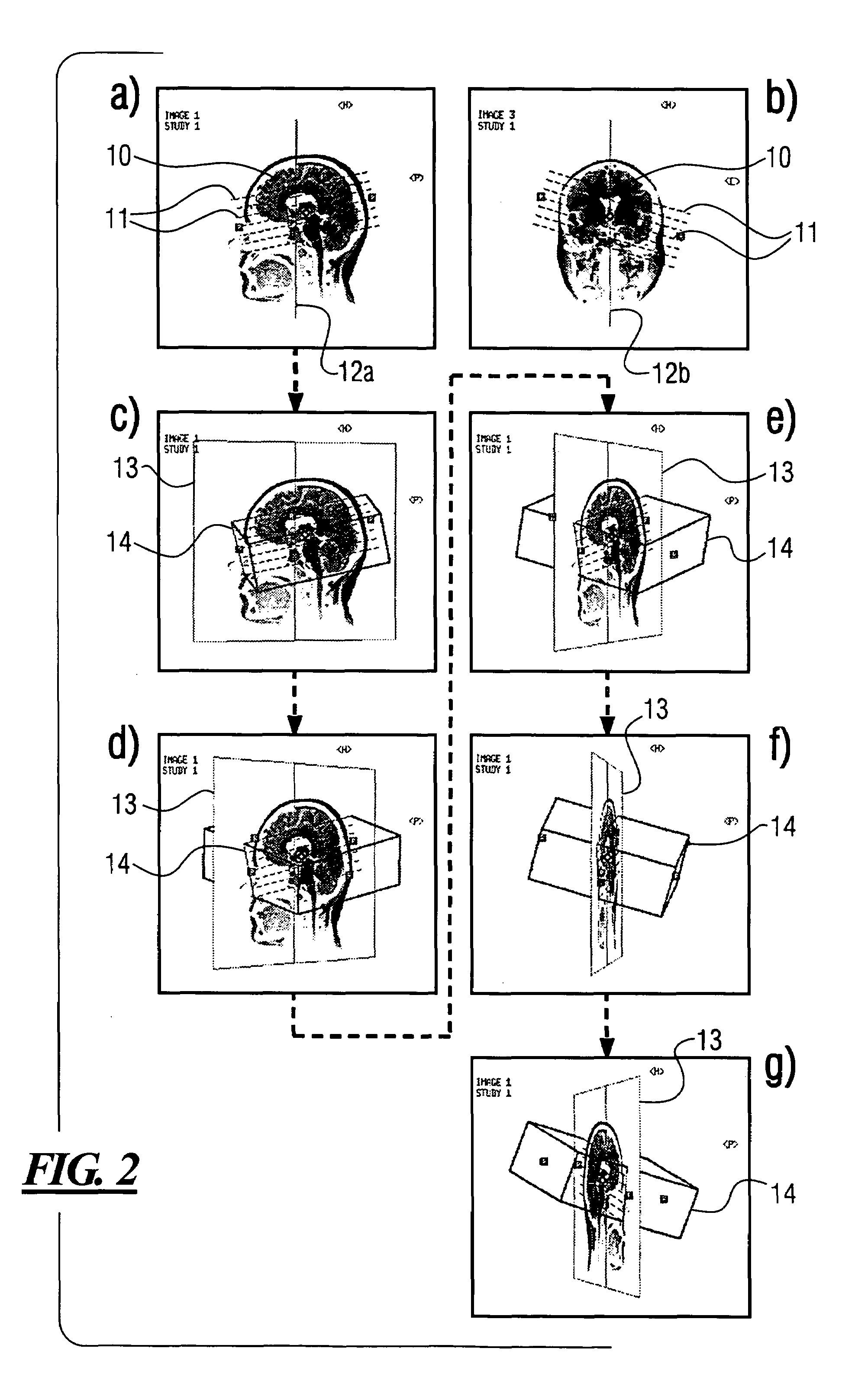
[0013]The apparatus according to the invention and the computer software product according to the invention enable a user to effect a significantly simplified positioning of slices to be measured with regard to a patient's body part to be measured, by means of a significantly improved display on the screen. Through the possibility of rotating the reference image together with the selected slices and the corresponding spatial representation of the slices, the position of the slices with regard to the reference image of the body part to be measured is visualized for the user in an extremely simple manner. In particular, the user can rotate the reference image as desired and observe the position of the slices from very different angles. This results in a series of major advantages for the user. The user understands the spatial relationships between the positioned slices and the reference image or the body part to be examined significantly faster. This saves a great deal of time which is required in conventional systems in order to conceptually reconstruct a spatial image using the sectional lines of the slices or in order to iteratively correct erroneous measurement and repeat it. Furthermore, the transition between different views of a spatial situation can easily be understood since the reference image together with the spatial representation of the slices can be adjusted practically in a continuously variable manner. The probability of slices being incorrectly positioned and therefore of an incorrect measurement being carried out is minimized. This makes it possible to minimize the burdens on the patient on account of the measurements both as to the examination time and the radiated energy. That is advantageous in particular in the case of magnetic resonance imaging examinations, which are very cost-intensive. Furthermore, the handling of the apparatus according to the invention and of the computer software product according to the invention is simple and easy to learn even for users who are not specially trained, and can be technically fully integrated into existing systems for graphical slice positioning. In this case, it is particularly advantageous that the effects of a change in the slices or the inclination thereof can immediately be visualized as to their effects with regard to the body part to be examined.
[0014]In an advantageous manner, the processing device generates a frame around the reference image and generates the rotated representation of the reference image with the frame as a rotated two-dimensional structure and represents the rotated representation of the reference image on the screen. Since the reference image has actually been measured, and is represented, as a two-dimensional structure, the frame advantageously serves to visualize the rotation of the reference image. The reference image is generally rotated about a center axis which, for example, may simultaneously be the sectional axis of a further reference image. The reference image can be rotated for example about a vertical center axis or else about a horizontal center axis. Furthermore, it is possible to rotate the reference image around arbitrarily inclined axes in order to visualize the spatial arrangement of the slices.
[0017]In an advantageous manner, the processing device represents in a distinguishable fashion the contour lines which face the observer when represented on the screen and the contour lines which are hidden to the observer. In this case, it is advantageous, in particular, if the contour lines which face the observer are represented in a visible fashion and the contour lines which are hidden to the observer are represented in an invisible fashion. The contour lines which are hidden to the observer are those contour lines of the slice group which, as it were, are concealed by the areas—facing the observer—of the three-dimensional representation of the contour lines. Furthermore, it is advantageous if the processing device does not represent the contour lines which lie behind the reference image including the frame when represented on the screen for the observer. These measures significantly reinforce the spatial effect of the representation.

Problems solved by technology

However, this description has a major disadvantage, namely that the sign rule for determining the direction of rotation, i.e. positive or negative, is very complicated and the risk of errors is correspondingly high.
Although the slices, such as e.g. the slices 11 of the slice group represented in FIGS. 2a and 2b, can be freely displaced and rotated via a corresponding input apparatus of the assigned data processing system, it is difficult even for practiced users to correctly interpret the actual position of the slices using the depicted sectional or projection lines in the reference images.

Method used


Image

  • Apparatus for reference image rotation, and computer software product and method for reference image rotation
  • Apparatus for reference image rotation, and computer software product and method for reference image rotation
  • Apparatus for reference image rotation, and computer software product and method for reference image rotation

Examples


Embodiment Construction

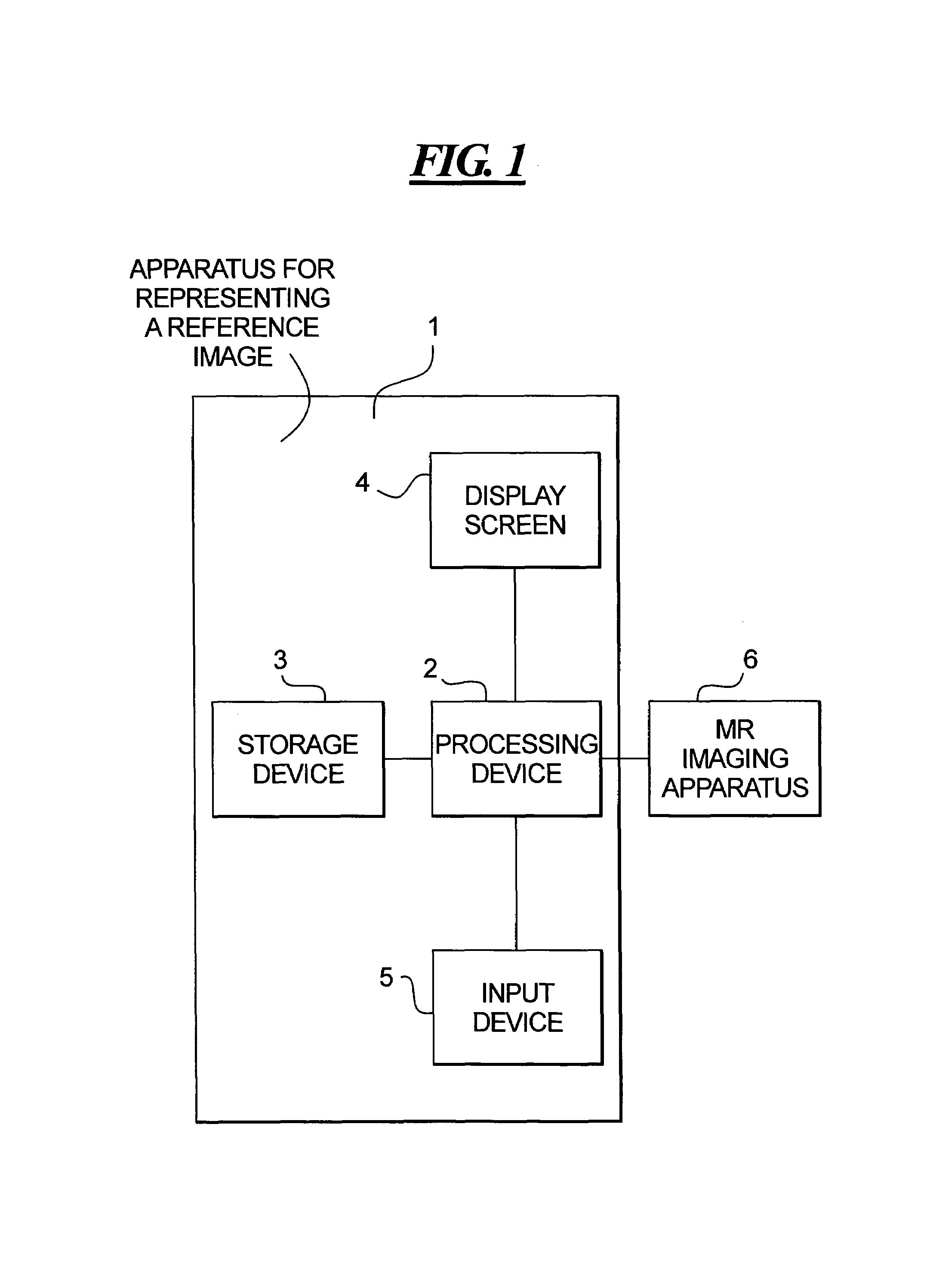
[0021]FIG. 1 is a schematic illustration of an apparatus 1 according to the invention for representing reference images of patients and slices to be measured in a displayed reference image for assisting the positioning of slices in preparation of a slice-by-slice measurement, for example by means of a magnetic resonance imaging apparatus 6. The apparatus 1 according to the invention is, for example, a data processing apparatus, such as a computer or the like, and comprises a processing device 2, a storage device 3, a screen 4 and an input device 5. Of course the apparatus 1 according to the invention has all further elements required for proper operation, such as e.g. clock generator, power supply, etc, however, these are not crucial for the functions according to the invention, and therefore are not represented for clarity.

[0022]The apparatus 1 according to the invention serves for displaying reference images and slice groups in order to prepare for an examination of a patient in a...


PUM


Abstract

In an apparatus for displaying reference images of patients and slices to be measured in a displayed reference image for assisting the positioning of slices in preparation for a slice-by-slice measurement and a computer software product and corresponding method, a storage device stores at least one measured reference image of a current patient, a display screen displays a stored reference image, an input device allows entry of commands for displaying and positioning slices to be measured in a displayed reference image, and a processing device processes the entered commands and correspondingly controls the display of the reference image and the slices. The processing device, depending on the entry of commands via the input device by a user, generates a rotated representation of the reference image and a spatial representation—corresponding to the rotation of the reference image—of the slices and displays them on the screen.

Description

BACKGROUND OF THE INVENTION[0001]1. Field of the Invention[0002]The present invention relates to an apparatus for representing reference images of patients, and slices to be registered in a represented reference image, for assisting the positioning of slices in preparation for a slice-by-slice data-acquisition, and to a computer software product for an apparatus of this type.[0003]2. Description of the Prior Art[0004]In so-called graphical slice positioning (GLP) to prepare for measurements and examinations by means of a magnetic resonance imaging apparatus, slices to be newly measured are planned on already measured images of a current patient. In this case, one or a plurality of so-called reference images of the current patient's body parts to be examined are recorded by the magnetic resonance imaging apparatus and represented on a screen. The slice-by-slice measurements to be carried out in the corresponding body part by means of the magnetic resonance imaging apparatus are plann...

Claims


Application Information

Patent Timeline
Patent Type & Authority Patents(United States)
IPC IPC(8): G09G5/34G01R33/32A61B5/055G06T1/00G06T3/60G06T15/08
CPCA61B5/055A61B5/0037A61B5/7425
Inventor HERGET, MARTINHARDER, MARTIN
Owner SIEMENS HEALTHCARE GMBH
Learn More