Cooling fluid pump and electric apparatus, such as personal computer, provided with the pump

Inactive Publication Date: 2006-03-21
KK TOSHIBA
View PDF10 Cites 42 Cited by
  • Summary
  • Abstract
  • Description
  • Claims
  • Application Information

AI Technical Summary

Benefits of technology

[0009]When the cooling fluid flows in the pump chamber with rotation of the impeller, heat generated by the heating element is absorbed via the casing into the fluid. In this case, since the axis of rotation of the impeller is located radially away from the center of the casing, a

Problems solved by technology

Consequently, the heating eleme

Method used


Image

  • Cooling fluid pump and electric apparatus, such as personal computer, provided with the pump
  • Cooling fluid pump and electric apparatus, such as personal computer, provided with the pump
  • Cooling fluid pump and electric apparatus, such as personal computer, provided with the pump

Examples


Example

[0018]One embodiment of the present invention will be described with reference to the drawings. The fluid pump of the invention is applied to a personal computer in the embodiment.

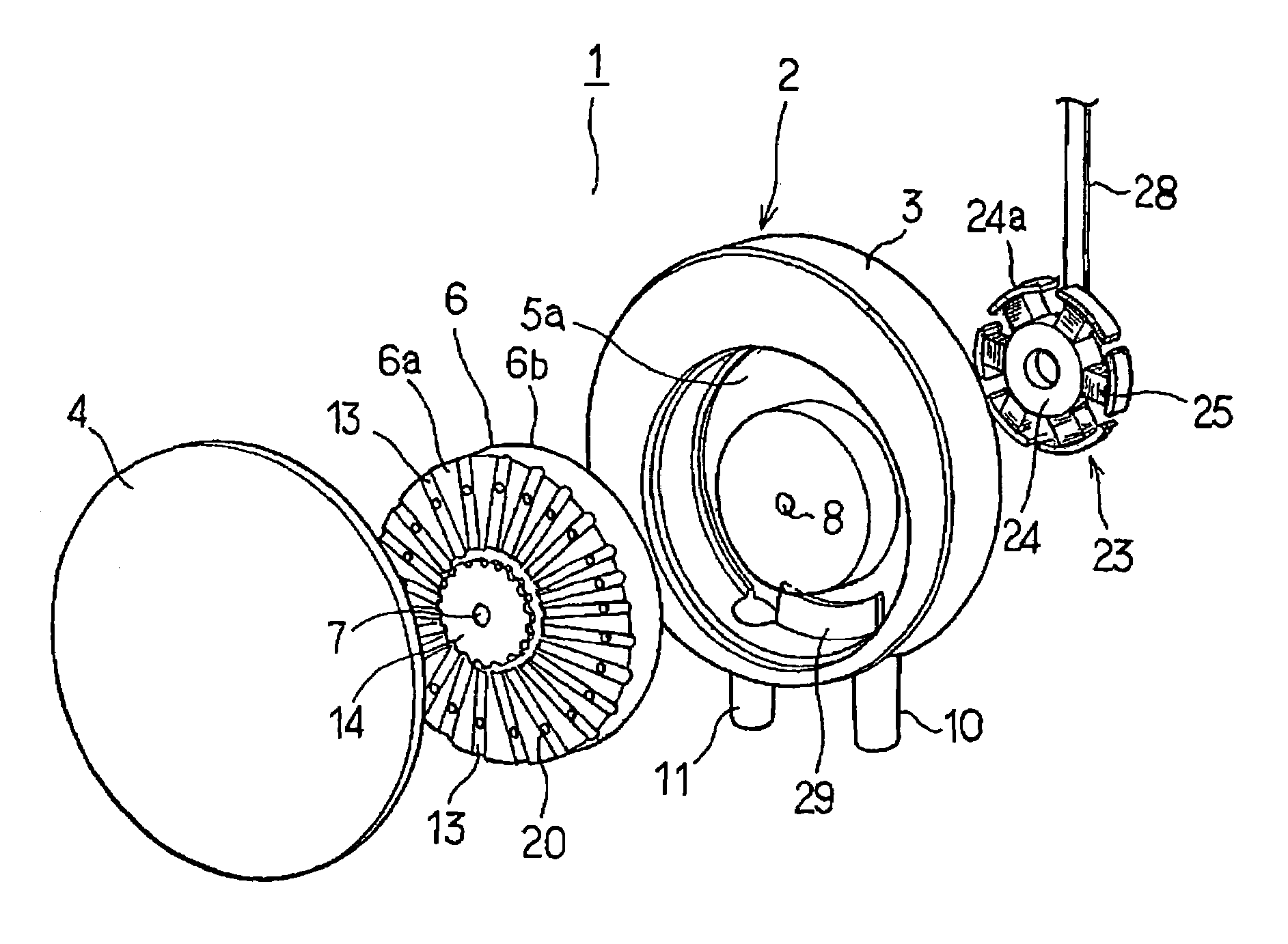
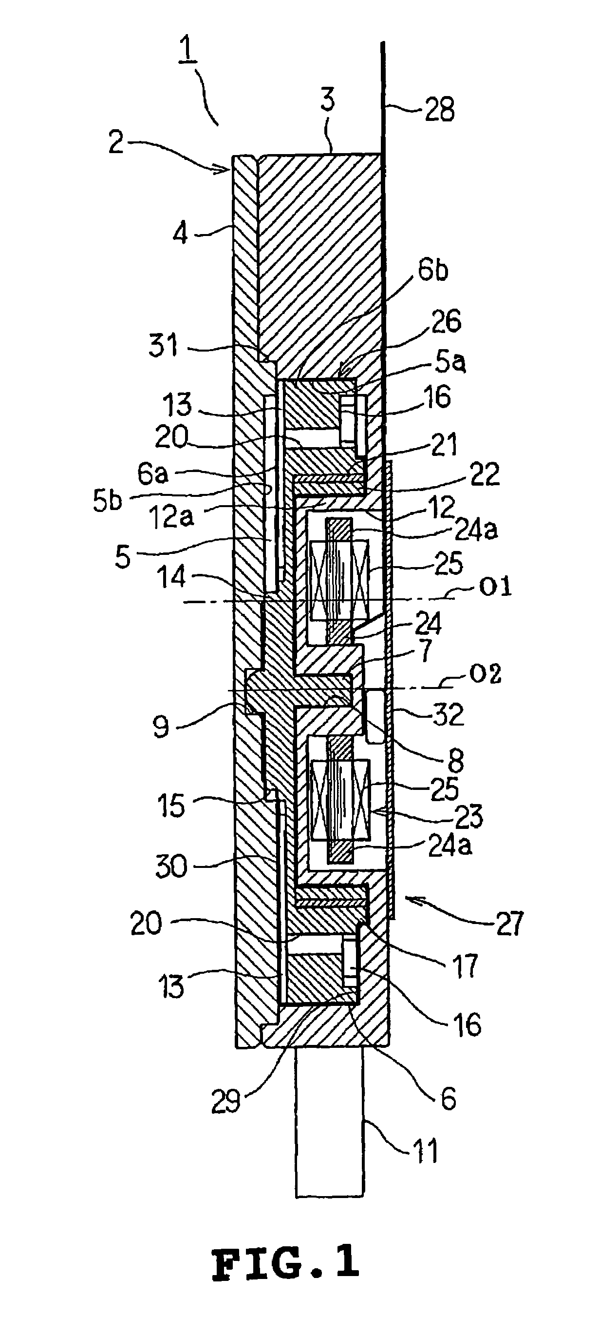
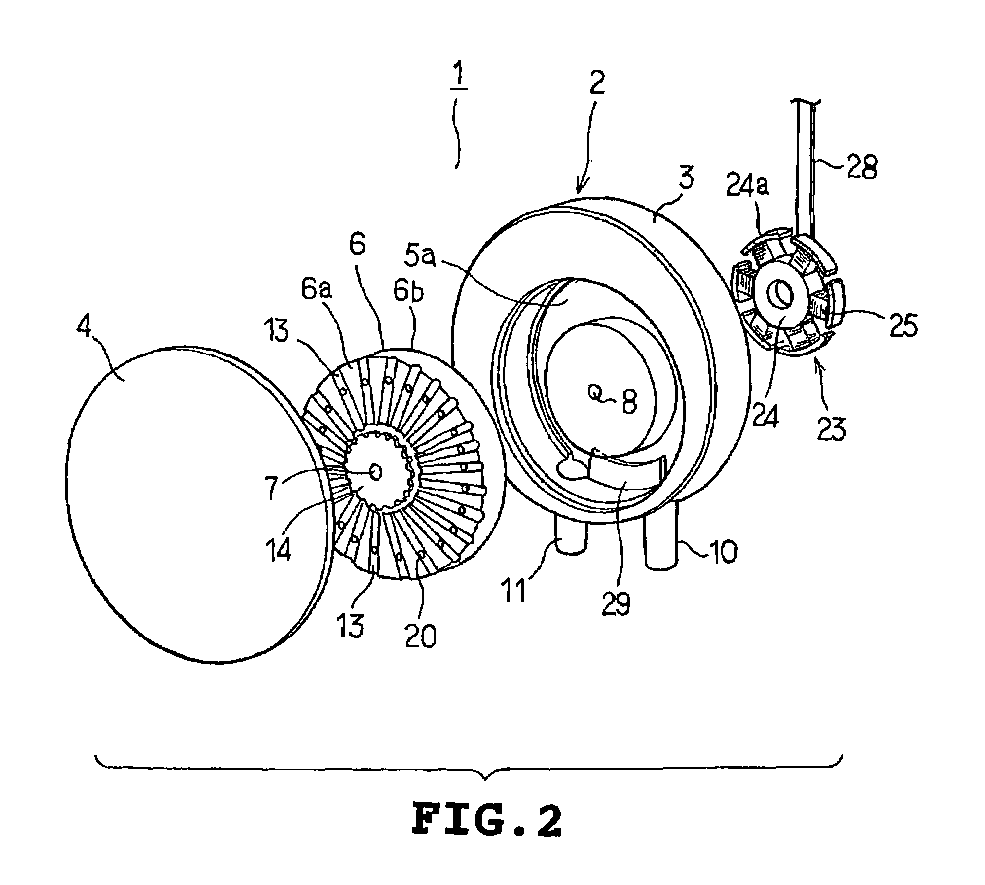
[0019]Referring to FIGS. 1 to 4B, the construction of the fluid pump will be described. The fluid pump 1 comprises a thin cylindrical casing 2 including first and second casings 3 and 4 and having a pump chamber 5 defined therein, and an impeller 6 rotatably mounted in the pump chamber 5. The first and second casings 3 and 4 are formed with concavities 5a and 5b respectively. Bearings 8 and 9 supporting a rotational shat 7 of the impeller 6 are provided in central portions of the concavities 5a and 5b respectively.

[0020]The pump chamber 5 is constructed so that the center thereof is located radially away from the center of the casing 2. More specifically, a straight line O2 passing the center of the pump chamber 5 and extending in parallel to the rotational shaft 7 of the impeller 6 is located radially awa...


PUM


Abstract

A cooling fluid pump in which a cooling fluid is caused to flow to cool a heating element includes a casing brought into a direct contact or an indirect contact via a heat transfer member with the heating element, a pump chamber defined in the casing, an impeller rotatably mounted in the pump chamber and including a pump groove formed in either one of both axial end faces, the impeller having an axis of rotation located radially away from a center of the casing, an inlet formed in the casing so that the cooling fluid is supplied through the inlet into the pump chamber by an action of the pump groove with rotation of the impeller, and an outlet formed in the casing so that the cooling fluid is discharged through the outlet out of the pump chamber by an action of the pump groove with rotation of the impeller.

Description

BACKGROUND OF THE INVENTION[0001]1. Field of the Invention[0002]This invention relates to a fluid pump cooling heating elements composing electric apparatus and personal computers.[0003]2. Description of the Related Art[0004]Japanese patent publications, JP-A-2001-123978 and JP-A-2001-132677, disclose conventional fluid pumps, for example. Each disclosed fluid pump comprises a casing having a pump chamber therein, an inlet and an outlet both formed in the casing, a disc-like impeller rotatably provided in the pump chamber and having pump grooves through which a liquid in the pump chamber is supplied to a peripheral interior of the pump chamber. Upon rotation of the impeller, the liquid is sucked through the inlet into the pump chamber by the action of the pump grooves and the liquid in the pump chamber is discharged from the outlet by the action of the pump grooves.[0005]When the foregoing fluid pump is used to cool a heating element of an electric apparatus, for example, the fluid ...

Claims


Application Information

Patent Timeline
IPC IPC(8): H05K7/20F04D13/02F04D5/00F04D29/42F04D29/58G06F1/20H02K5/04H02K21/22
CPCF04D5/002F04D29/588G06F1/203G06F2200/203G06F2200/201F04D29/586F04D5/00
Inventor ITO, KENICHISEKO, KATSUYA
Owner KK TOSHIBA
Why Eureka
Try Eureka