Magnetooptical recording apparatus having retreatable magnetic head

a recording apparatus and magnetic head technology, applied in the direction of maintaining the head carrier alignment, light beam reproducing, instruments, etc., can solve the problems of reducing the size of the recording apparatus, requiring a large arm height, and affecting the deflection of the disk surface, so as to achieve the effect of reducing the siz

Inactive Publication Date: 2006-03-21
CANON KK
View PDF17 Cites 8 Cited by
  • Summary
  • Abstract
  • Description
  • Claims
  • Application Information

AI Technical Summary

Benefits of technology

[0014]The present invention has been made in view of the above-mentioned problems with the conventional art, and therefore an object of the present invention is to provide a magnetooptical recording apparatus in which the displacement of a magnetic head in the tangential direction can be suppressed and which can also be reduced in size.

Problems solved by technology

The amount of the vertical movement thus required is a factor that limits thickness reduction of the apparatus and the like, and a height of from a movable support point of the magnetic head to the magnetooptical disk recording surface and a length of the magnetic head support portion adversely affect the disk surface deflection as a displacement in the tangential direction.
Therefore, the height distance must be made as small as possible, but in the conventional structure, because the magnetic head is so structured as to be supported by the movable arm, the height of the arm is required to some degree and thus the displacement of the magnetic head in the tangential direction cannot be avoided.

Method used


Image

  • Magnetooptical recording apparatus having retreatable magnetic head
  • Magnetooptical recording apparatus having retreatable magnetic head
  • Magnetooptical recording apparatus having retreatable magnetic head

Examples


first embodiment

(First Embodiment)

[0037]FIG. 4 is a plan view showing the structure of a magnetooptical recording apparatus in accordance with the present invention, FIG. 5 is a side view thereof, and FIG. 6 is a perspective view thereof.

[0038]In the figure, reference numeral 100 denotes a magnetooptical disk cartridge (hereinafter referred to as “cartridge”), and 100a is a magnetooptical disk that is received in the cartridge 100. Reference numeral 101 denotes a chassis main body which serves as the structural basis of the apparatus, and 102 is a cartridge holder that holds the cartridge 100. In this example, assuming that an upper right side end portion of the drawing is a rear end portion of the chassis main body 101 in FIG. 6, support portions 101a for opening and closing the cartridge holder 102 are disposed on both end portions of the rear end portion of the chassis main body 1. Each of the support portions 101a is bent at a right angle with respect to the horizontal plane of the chassis main...

second embodiment

(Second Embodiment)

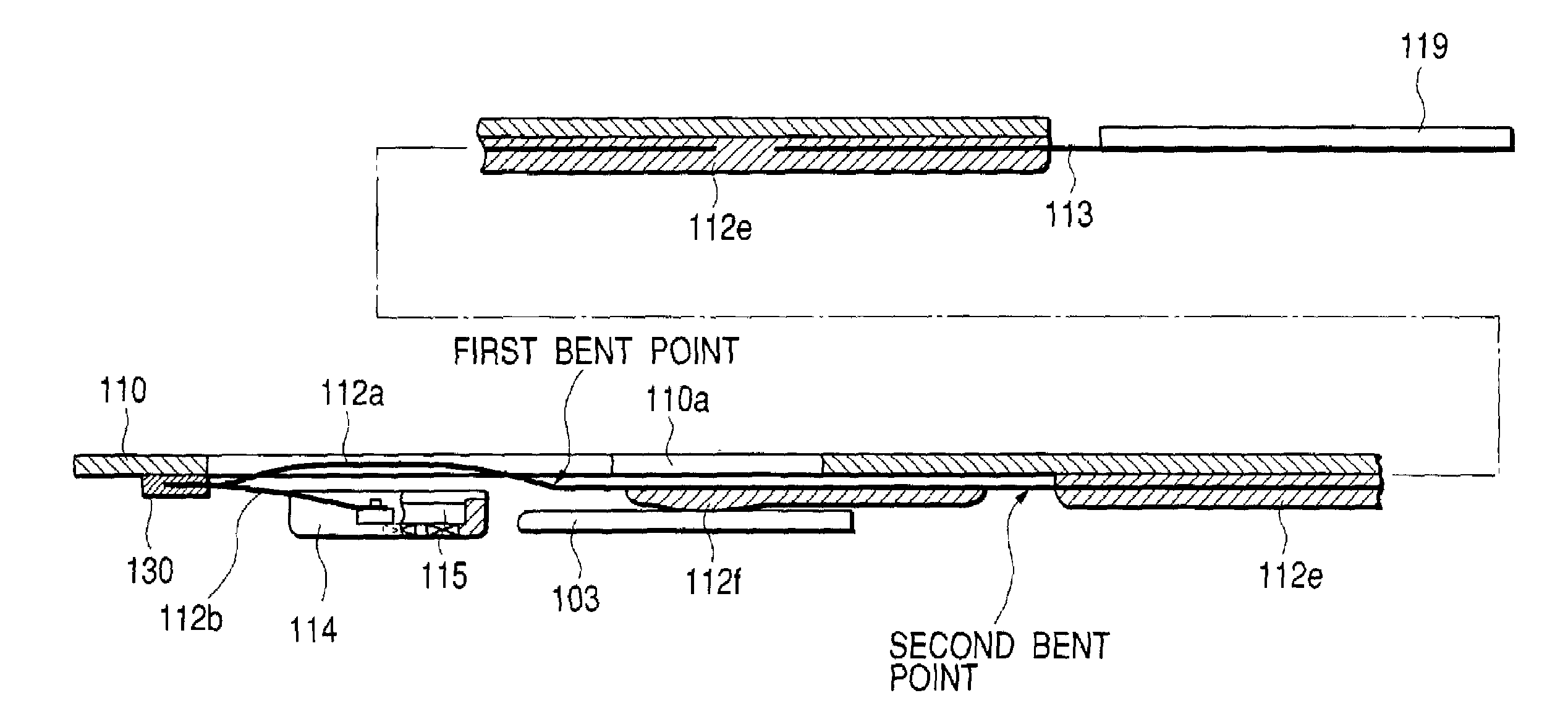
[0061]The difference of a second embodiment from the above-mentioned first embodiment resides in the support structure for the magnetic head, and the structures indicated by identical reference numerals show structures having the same functions, and description thereof will be omitted.

[0062]FIG. 12 shows a plan view of a magnetic head portion, FIG. 13 shows a state at the time of loading, and FIG. 14 shows a state at the time of unloading. FIGS. 13 and 14 show the periphery of the magnetic head as viewed from the side surface. First, FIG. 13 shows a state in which the magnetic head slider 114 is abutted against the disk surface, and the magnetic head slider 114 is urged through the elastic members 112a and 112b so as to be in contact with the disk surface with a given contact pressure.

[0063]A magnetic pole core 115a and a coil 115b (wound around the core) of desired sizes are built in the magnetic head slider 114 and integrally formed with the magnetic head slider...


PUM

PropertyMeasurementUnit
magnetic fieldaaaaaaaaaa
displacementaaaaaaaaaa
thicknessaaaaaaaaaa

Abstract

A magnetooptical recording apparatus that records information by applying a magnetic field from a magnetic head while irradiating a light beam onto a magnetooptical disk from an optical pickup. The apparatus includes an optical pickup, a magnetic head having a slider that moves in a radial direction of the magnetooptical disk together with the optical pickup and is abutted against a recording surface of the magnetooptical disk and first and second elastic members that support the magnetic head.

Description

BACKGROUND OF THE INVENTION[0001]1. Field of the Invention[0002]The present invention relates to a magnetooptical recording apparatus that records information on a magnetooptical disk, and more particularly to an improvement in a magnetic head that slides on the magnetooptical disk.[0003]2. Related Background Art[0004]Up to now, there has been known a magnetooptical disk recording / playback apparatus that records or plays back information with respect to a magnetooptical disk having a magnetooptical recording layer which is formed of a vertically magnetized film as a recording medium. The recording system of the magnetooptical disk recording / playback apparatus is roughly classified into a magnetic field modulation system and a light modulation system. Of those systems, in the magnetic field modulation system, an orientation of an external magnetic field is reversed in accordance with information to be recorded while irradiating a laser beam having a desired intensity, to thereby reco...

Claims


Application Information

Patent Timeline
Patent Type & Authority Patents(United States)
IPC IPC(8): G11B11/10B29C45/14G11B5/48G11B5/58G11B11/00G11B11/105G11B17/04
CPCG11B11/10558G11B17/046G11B11/10571G11B11/1058
Inventor SUZUKI, KAZUNORI
Owner CANON KK
Why Eureka
Try Eureka