
Control method for a vehicle having an engine and an accessory device

a control method and accessory device technology, applied in electric control, lighting and heating apparatus, instruments, etc., can solve the problems of reducing comfort, reducing fuel economy, and reducing comfort during clutch engagement, so as to improve fuel economy and improve drive feel

Inactive Publication Date: 2006-03-28
FORD GLOBAL TECH LLC
View PDF20 Cites 22 Cited by
  • Summary
  • Abstract
  • Description
  • Claims
  • Application Information

AI Technical Summary

Benefits of technology

[0008]An object of the present invention is to provide methods for controlling engagements of an air conditioning compressor coupled to an internal combustion engine capable of improving fuel economy and / or improving drive feel.

Problems solved by technology

First, driver comfort is degraded during clutch engagements during some driving conditions.
In other words, during some driving conditions, clutch engagements are felt strongly by vehicle operators and comfort is therefore degraded.
Second, optimum fuel economy is not obtained since compressor cycling engagement is not coordinated to vehicle and engine operating conditions.

Method used


Image

  • Control method for a vehicle having an engine and an accessory device
  • Control method for a vehicle having an engine and an accessory device
  • Control method for a vehicle having an engine and an accessory device

Examples


Embodiment Construction

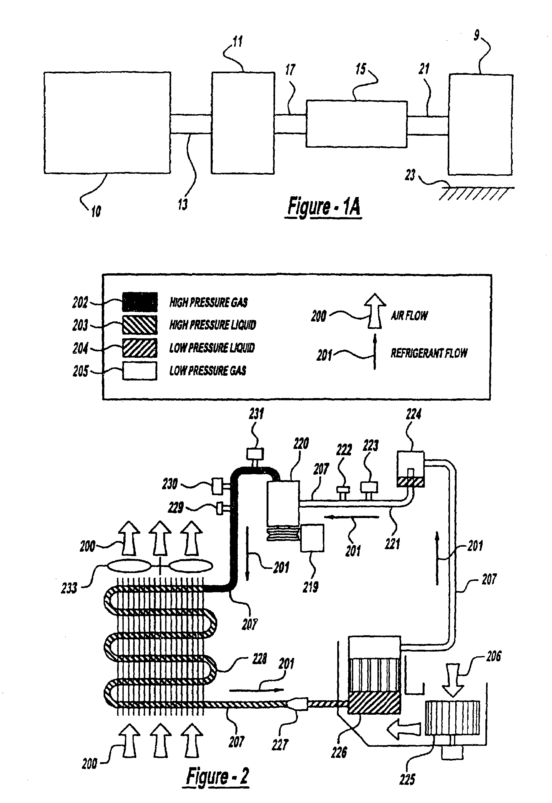
[0025]Referring to FIG. 1A, internal combustion engine 10, further described herein with particular reference to FIG. 1B, is shown coupled to torque converter 11 via crankshaft 13. Torque converter 11 is also coupled to transmission 15 via turbine shaft 17. Torque converter 11 has a bypass clutch (not shown) which can be engaged, disengaged, or partially engaged. When the clutch is either disengaged or partially engaged, torque converter 11 is said to be in an unlocked state. Turbine shaft 17 is also known as transmission input shaft. Transmission 15 comprises an electronically controlled transmission with a plurality of selectable discrete gear ratios. Transmission 15 also comprises various other gears such as, for example, a final drive ratio (not shown). Transmission 15 is also coupled to tire 19 via axle 21. Tire 19 interfaces the vehicle (not shown) to the road 23.

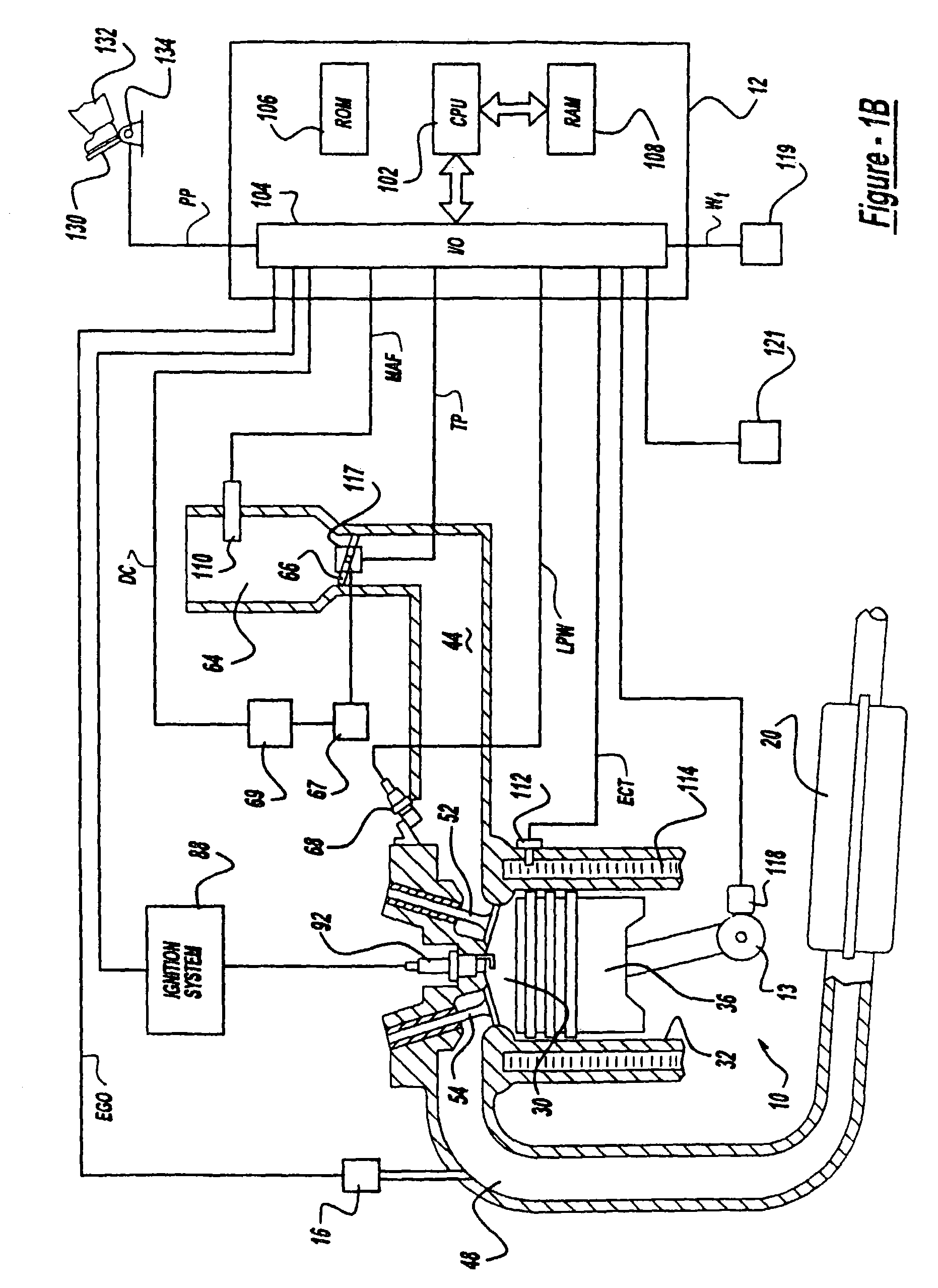
[0026]Internal combustion engine 10 comprising a plurality of cylinders, one cylinder of which is shown in FIG. 1B,...


PUM


Abstract

A method for controlling cycling of an air conditioning compressor coupled to an internal combustion engine interrupts normal cycling based on operation conditions. In addition, normal engaged and disengaged cycling durations are adaptively estimated in real-time. The method of the present invention achieves improved fuel economy and improved drive feel. As an example, improved fuel economy is achieved by engaging the compressor during braking or when the engine is being driven by the vehicle. As another example, improved drive feel is achieved by engaging the compressor during transient conditions when drive feel is unaffected.

Description

CROSS-REFERENCE TO RELATED APPLICATIONS[0001]This application is a continuation application of Ser. No. 10 / 087,870 filed Mar. 1, 2002 now U.S. Pat. No. 6,601,295 which application is a divisional application of Ser. No. 09 / 482,447 filed Jan. 13, 2000 now U.S. Pat. No. 6,755,032, and are hereby incorporated in their entireties for all purposes.FIELD OF THE INVENTION[0002]The field of the invention relates generally to air conditioning system control coordinated with engine control.BACKGROUND OF THE INVENTION[0003]Vehicles are typically equipped with an air conditioning system to provide cabin cooling and to dry air for dehumidifying functions. Air conditioning systems typically include a compressor driven by a vehicle's internal combustion engine. The compressor can be either engaged, fully or partially, or disengaged to the engine via an electronically controlled clutch.[0004]During air conditioning system operation under certain operating conditions, the compressor cycles between a...

Claims


Application Information

Patent Timeline
Patent Type & Authority Patents(United States)
IPC IPC(8): B60H1/32F02D41/08
CPCB60H1/3208F02D41/083B60H1/3216
Inventor KOTWICKI, ALLAN JOSEPHBLAHA, GEORGEDAGE, GERHARD A.RUSSELL, JOHN DAVIDCULLEN, MICHAEL JOHN
Owner FORD GLOBAL TECH LLC
Learn More