Reinforced hose

a technology of reinforced hoses and hoses, applied in the direction of vehicular safety arrangements, pedestrian/occupant safety arrangements, other domestic objects, etc., can solve the problems of inferior expansion resistance, low stretchability, and excellent durability of high stretchability

Active Publication Date: 2006-03-28
TOYODA GOSEI CO LTD
View PDF11 Cites 8 Cited by
  • Summary
  • Abstract
  • Description
  • Claims
  • Application Information

AI Technical Summary

Benefits of technology

[0009]Upon such circumstances, an object of the invention is to provide a brake hose in which both durability and expansion resistance (the amount of volumetric expansion) can be improved on the basis of examination of the braid angle of reinforcing yarn in each reinforcing layer.
[0012]The polyester yarn having a tensile strength of not lower than 6.9 g per unit dtex and having a stretchability of 2.6±1.0% at 2.7 g load per unit dtex can be used as the reinforcing yarn. The polyester yarn may comprise a high-modulus PET yarn having a tensile strength of not lower than 6.9 g per unit dtex and having a stretchability of 2.6±1.0% at 2.7 g load per unit dtex. Thus, high durability and low volumetric expansion against repeated load can be combined successfully with each other. That is, because the high-modulus PET yarn is lower in expansion per predetermined load than ordinary PET yarn which has a tensile strength of not lower than 6.6 g per unit dtex and has a stretchability of 4.0±1.0% at 2.7 g load per unit dtex, the amount of volumetric expansion can be reduced. In addition, because polyester yarn is used in place of vinylon yarn in the lower yarn layer (or the upper yarn layer), the reinforcing layers are also excellent in fatigue resistance. The term “unit dtex” used herein means the number of grams per 10,000 m of filament yarn.
[0016]In a preferred embodiment, the thickness of the inner rubber layer is preferably set at 0.6±0.2 mm, especially preferably set at 0.6±0.1 mm. When the thickness of the inner rubber layer is set at a small value, the outer diameter of the inner rubber layer can beset at a small value. Accordingly, the reinforcing layers can be braided on the inner rubber layer densely and firmly though the amount of reinforcing yarn is small As a result, the slack or gap between pieces of reinforcing yarn can be reduced, so that the amount of volumetric expansion can be reduced. Although the function of reducing the amount of volumetric expansion becomes more intensive as the thickness of the inner rubber layer becomes smaller, the inner rubber layer can be hardly extrusion-molded or the pressure fluid may penetrate into the inner rubber layer if the thickness of the inner rubber layer is smaller than 0.4 mm. It is therefore preferable that the thickness of the inner rubber layer is not smaller than 0.4 mm.
[0017]In a preferred embodiment, the reinforcing yarn has a size of 1,100±100 dtex. In this case, each reinforcing layer with a small outer diameter can be formed so densely that the amount of volumetric expansion can be reduced.

Problems solved by technology

However, fiber yarn having a high stretchability is excellent in durability but inferior in expansion resistance whereas fiber yarn having a low stretchability is excellent in expansion resistance but inferior in durability.
That is, durability and expansion resistance are contrary to each other.

Method used


Image

  • Reinforced hose
  • Reinforced hose
  • Reinforced hose

Examples


Embodiment Construction

[0025]A preferred embodiment of the invention will be described below to make the aforementioned configuration and operation of the invention clearer.

(1) schematic structure of Brake Hose 10

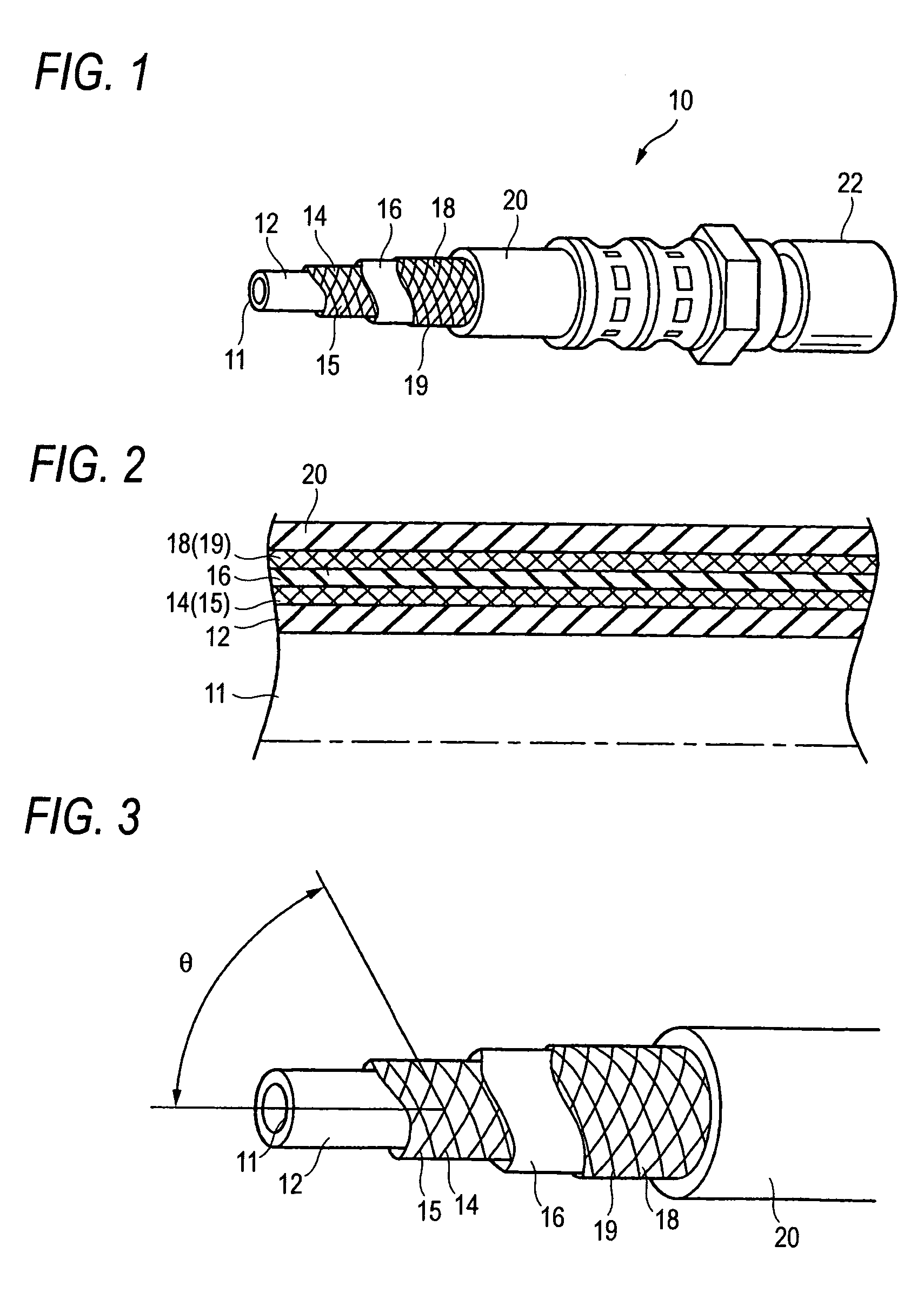
[0026]FIG. 1 is a partly cutaway perspective view showing an embodiment in which are inforced hose according to the invention is applied to a brake hose 10. FIG. 2 is a half-sectional view of the brake hose 10. In FIGS. 1 and 2, the brake hose 10 is used so that a master cylinder used in a vehicle oil pressure brake not shown can be connected to a tire side hydraulic device by the brake hose 10. The brake hose 10 is formed as a laminate of five layers so that the brake hose 10 can bear the pressure of brake fluid. That is, the brake hose 10 has: an inner rubber layer 12 including a flow path 11; a lower yarn layer 14; an intermediate rubber layer 16; an upper yarn layer 18; and an outer rubber layer 20; wherein a mouse piece 22 is tightened to an end portion of the brake hose by caulking.

(2) Laye...


PUM

PropertyMeasurementUnit
repose angleaaaaaaaaaa
braid angleaaaaaaaaaa
thicknessaaaaaaaaaa

Abstract

A brake hose has an inner rubber layer, an outer rubber layer, and at least two reinforcing layers provided between the inner rubber layer and the outer rubber layer. The reinforcing layers include an upper yarn layer, and a lower yarn layer. Polyester yarn having a tensile strength of not lower than 6.9 g per unit dtex and having a stretchability of 2.6±1.0% at 2.7 g load per unit dtex is used as lower yarn in the lower yarn layer. The braid angle of the lower yarn layer with respect to the axial direction of the hose is set at 59±2°.

Description

[0001]This application is based on Japanese Patent Application No. 2003-352509, which is incorporated herein by reference.BACKGROUND OF THE INVENTION[0002]1. Field of the Invention[0003]The present invention relates to a reinforced hose having an inner rubber layer, an outer rubber layer, and at least two reinforcing layers including an upper yarn layer and a lower yarn layer.[0004]2. Description of the Related Art[0005]Of this type reinforced hoses, a hose shown in FIG. 7 is heretofore known as a brake hose used in a vehicle. FIG. 7 is a sectional view showing important part of the brake hose 100 according to the related art. The brake hose 100 is formed in such a manner that a plurality of rubber and fiber yarn layers are laminated because the brake hose 100 needs to have high pressure resistance to brake oil pressure. That is, the brake hose 100 is formed as a laminate which has: an inner rubber layer 102 for forming a flow path 101 in which brake oil flows; a lower yarn layer 10...

Claims


Application Information

Patent Timeline
Patent Type & Authority Patents(United States)
IPC IPC(8): F16L11/08B32B1/08B32B25/02
CPCF16L11/086Y10T428/1362Y10T428/1366
Inventor ONO, MITSUGUMIZUTANI, SATOSHIFURUI, KENICHIROMURAKAMI, YUICHIRO
Owner TOYODA GOSEI CO LTD
Why Eureka
Try Eureka