Powder supplying apparatus and powder molding apparatus

Inactive Publication Date: 2006-03-28
MURATA MFG CO LTD
View PDF19 Cites 17 Cited by
  • Summary
  • Abstract
  • Description
  • Claims
  • Application Information

AI Technical Summary

Benefits of technology

[0119]Making the blade tip of the scraping blade to be at an acute angle as to the surface of the die upon which scraping blade slides allows the excess powder material outside the molding space to be smoothly scraped off without causing the powder material to scatter, the face of the scraped powder material can be made uniform, and irregularities in the density of powder filling and the amount of supplying can be prevented.
[0120]Forming the scraping blade of a ceramic material suppresses wear of the blade tip even after repeated scraping operations, thus extending the life thereof as compared to conventional arrangements wherein felt is applied.
[0121]Offsetting the powder supplying tube outwards from the center of the powder injecting hole keeps the pressure due to change in the amount of the powder remaining within the hopper from directly acting upon the powder injecting hole, thereby preventing irregularities in powder density within the powder storing unit, thus preventing irregularities in filling density. Also, passing the powder supplying tube through the ceiling of the powder storing unit to be inserted to the inside thereof, so space can be left within the powder storing unit, suppressing change in the density of powder in the powder storing unit due to change in the amount of powder remaining in the hopper, also preventing irregularities in filling density. Further, offsetting the powder supplying tube outwards from the center of the p

Problems solved by technology

However, increasing the rotating speed of the rotating base could conceivably result in molded articles falling or shifting due to the force of inertia or the like acting thereupon, and accordingly it has been supposed that high-speed transporting might not be able to be realized.
Accordingly, the mold must be designed according to the track rail, which has been a problem in that the degree of freedom in the molding process has been small.
Also, with the

Method used


Image

  • Powder supplying apparatus and powder molding apparatus
  • Powder supplying apparatus and powder molding apparatus
  • Powder supplying apparatus and powder molding apparatus

Examples


Embodiment Construction

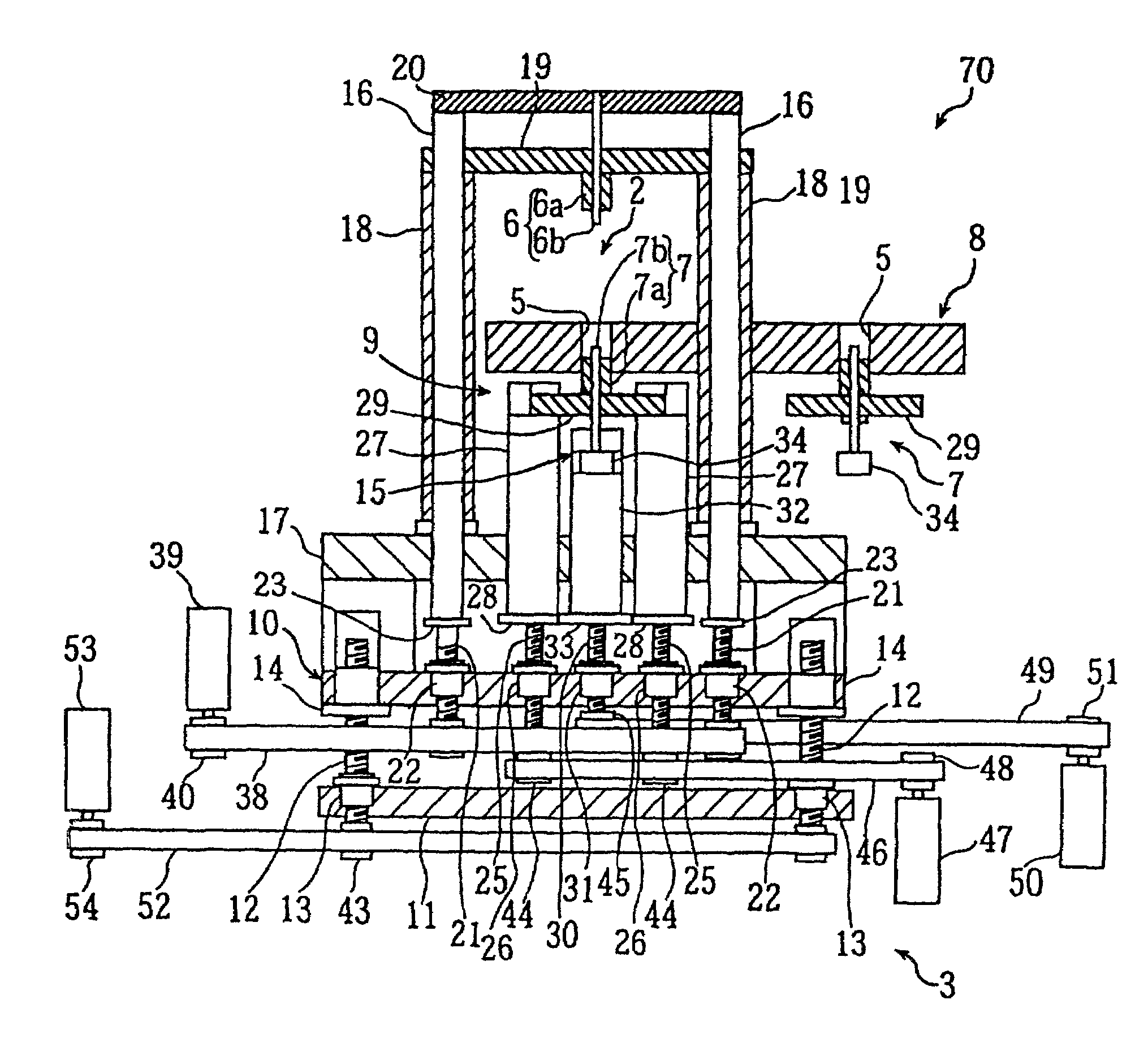
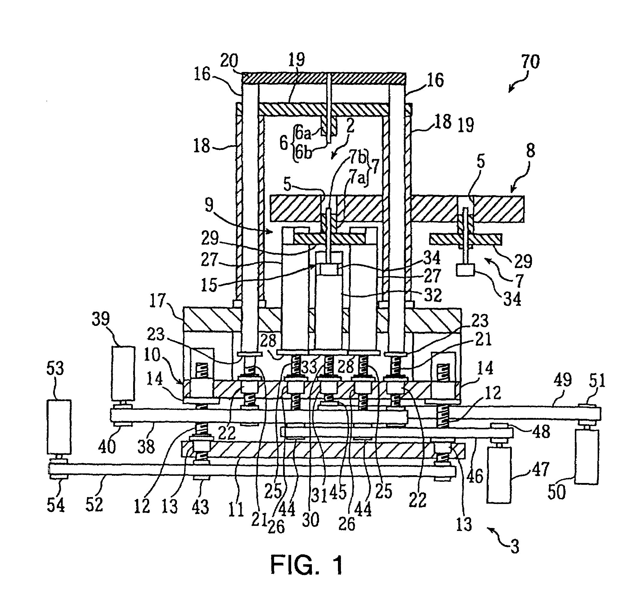
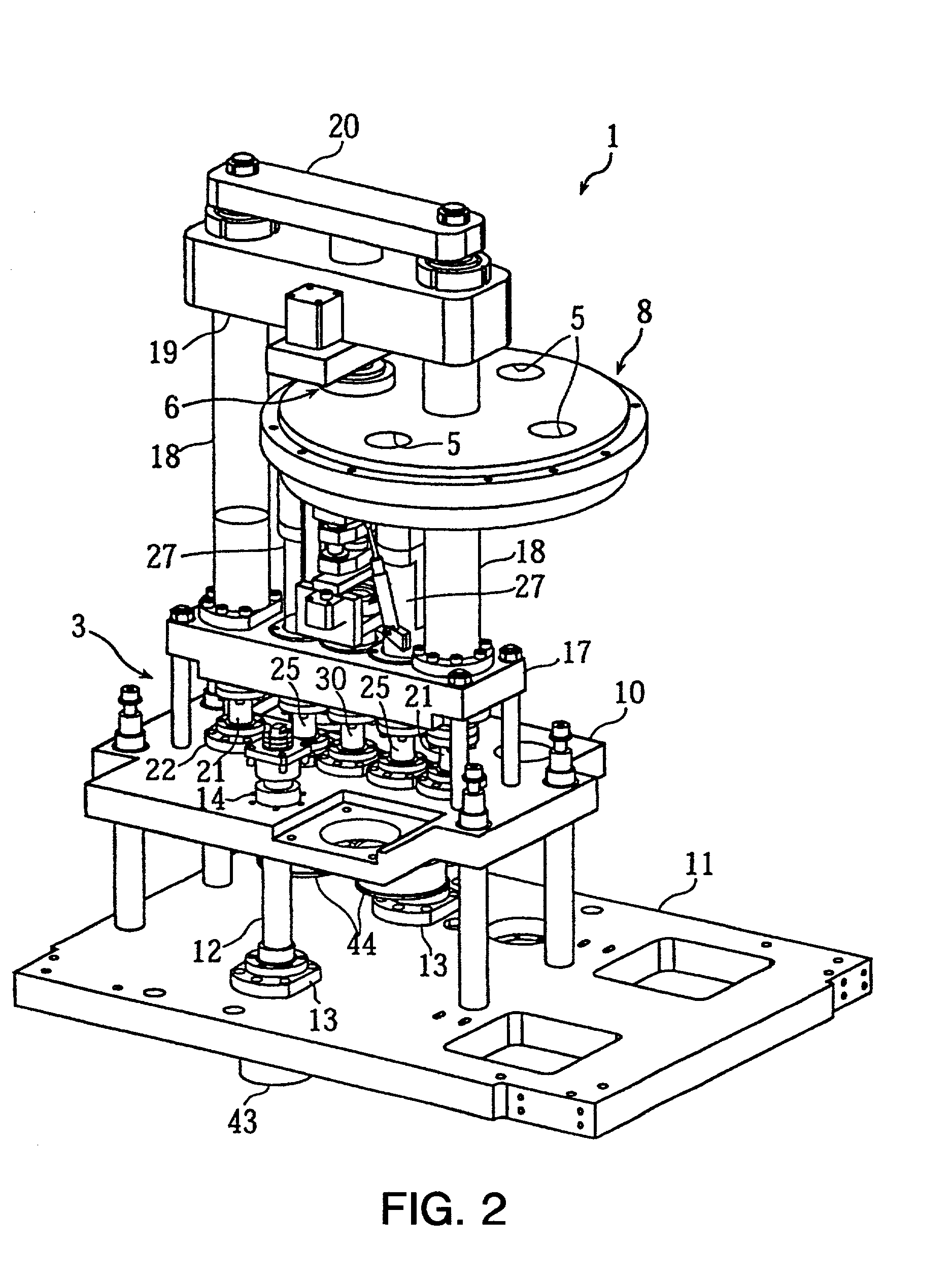
[0181]FIGS. 1 through 15B are diagrams describing a powder molding apparatus according to a first embodiment of the present invention. FIGS. 1 and 2 are a schematic configuration diagram and perspective view of the powder molding apparatus, FIG. 3 is a plan view illustrating the rotating action of the transporting table, FIGS. 4A through 4D are diagrams illustrating the action of the powder injecting mechanism, FIGS. 5 and 6 are cross-sectional views of the molding positioning means of the mold, FIGS. 7A and 7B are cross-sectional views of the elevating driving mechanism of the tapered block, FIGS. 8, 9A and 9B, and 10A and 10B, are a disassembled perspective view, perspective diagrams, and cross-sectional views of the linking means; FIGS. 11 and 12 are a cross-sectional view and plan view of unit holding means, and FIGS. 13A through 15B are diagrams illustrating the state of the lower punch unit holding a molded article.

[0182]In the figures, reference numeral 1 denotes a powder mol...


PUM

PropertyMeasurementUnit
Pressureaaaaaaaaaa
Angleaaaaaaaaaa
Speedaaaaaaaaaa

Abstract

A powder molding apparatus comprises a mold comprising a die having a powder molding space and upper and lower punch units, and a compression driving mechanism for performing compression molding by driving the upper and lower punch units independently, wherein molded articles formed by the compression molding are held by engaging lower first and second punches serving as a formed article holding mechanism at the time of transporting the molded articles. Thus, the molded articles can be prevented from falling or shifting while being transported between stages, thereby providing a powder molding apparatus capable of high speeds.

Description

BACKGROUND OF THE INVENTION[0001]1. Field of the Invention[0002]The present invention relates to a powder molding apparatus for performing compression molding of powder material such as ceramics, foods, medicines, etc., using a mold formed of a die and upper and lower punch units.[0003]2. Description of the Related Art[0004]An example of such a powder molding apparatus is proposed in Japanese Patent No. 2695757, for example. This powder molding apparatus is configured so as to transport a rotating base upon which multiple molds are disposed over a powder supplying unit, compression molding unit, and product extracting unit, in that order, by means of a cam follower and track rail. This apparatus enables consecutive production of molded articles, thereby improving productivity.[0005]Also, such powder molding apparatuses have in some cases conventionally used a rotating clamp mechanism which rotates in the same direction as the direction of compression driving as a clamp mechanism for...

Claims


Application Information

Patent Timeline
IPC IPC(8): B29C43/02B30B11/00B30B15/00B30B15/30
CPCB30B15/302B30B15/0017B30B11/00
Inventor KITAMURA, MAKOTOTAKAHASHI, SHIGEKIHIGAKI, TADANORIODA, YOSHIOSAI, KOUKITAKEUCHI, SHIGEYUKI
Owner MURATA MFG CO LTD
Why Eureka
Try Eureka