
Coaxial connector for circuit boards

a technology of coaxial connectors and circuit boards, which is applied in the direction of coupling device details, coupling device connections, two-pole connections, etc., can solve the problems of pcbs being oftentimes damaged and the current state of the art connectors are not ideal, so as to facilitate the mating of the ground interface member and facilitate the flex of the radial spring member

Inactive Publication Date: 2006-03-28
NORTH SOUTH HLDG
View PDF6 Cites 54 Cited by
  • Summary
  • Abstract
  • Description
  • Claims
  • Application Information

AI Technical Summary

Benefits of technology

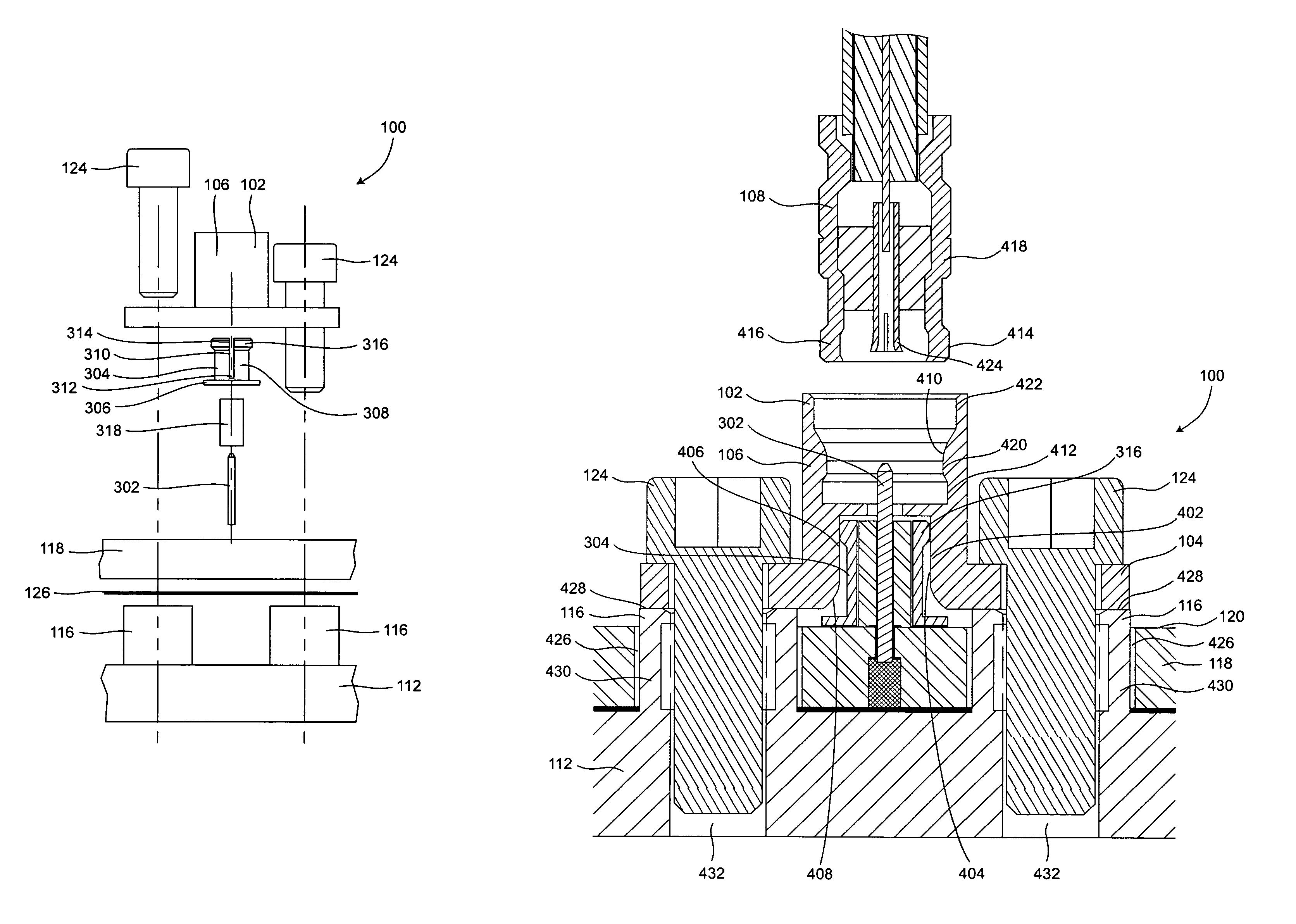
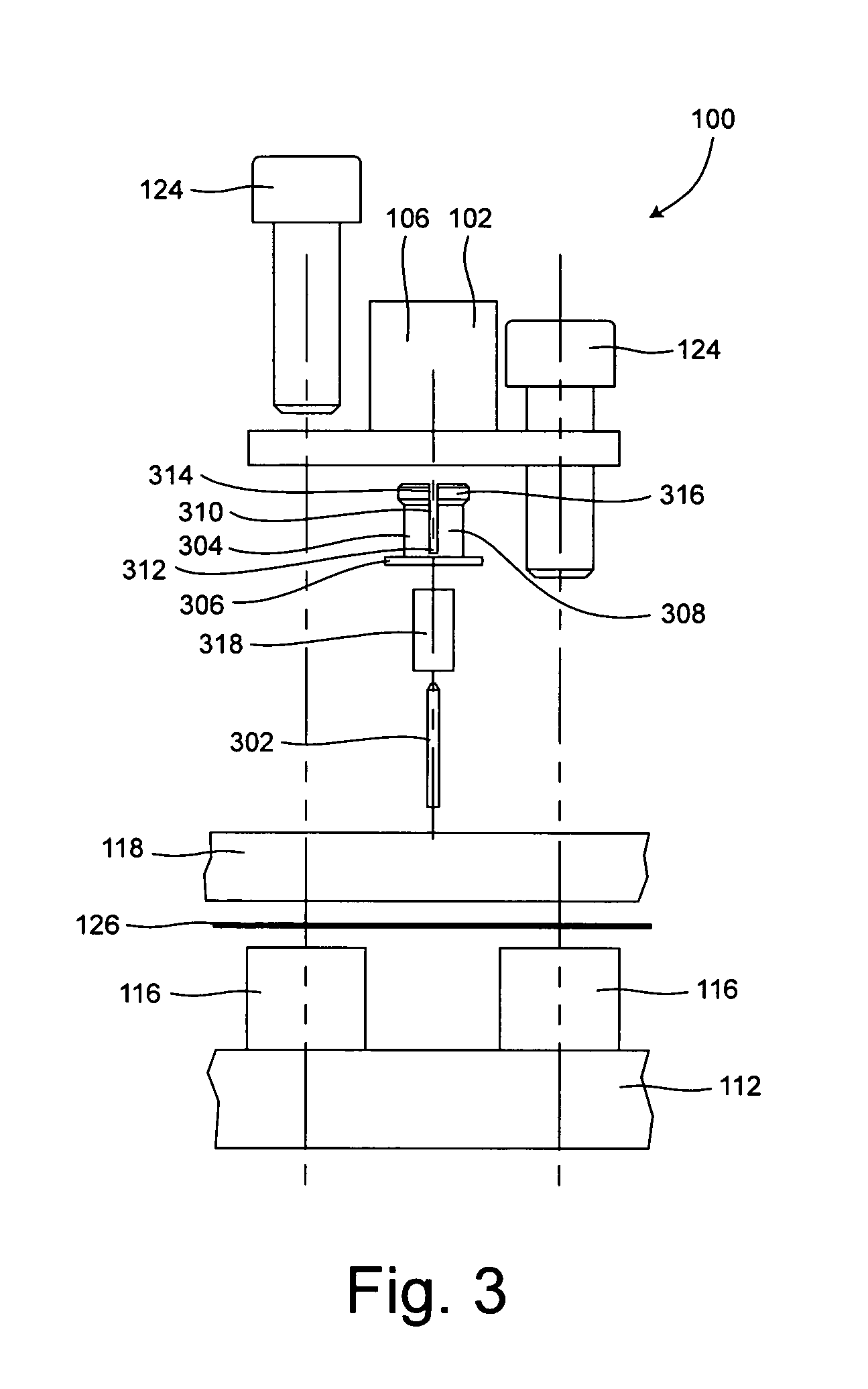
[0005]The present invention relates to a durable coaxial connector (hereinafter “connector”) for providing a reliable signal connection to a printed circuit board (PCB) while isolating the PCB from mechanical loads that are applied to the connector. The connector can include a connector body having a connector interface member suitable for mating with another connector. The connector also can include a flange, a ground interface receptacle and a ground interface member. The ground interface member can provide an electrically conductive ground path from the PCB to the connector interface member, and can include a first portion configured to be fixedly attached to a printed circuit board and a second portion configured to slideably mate to the ground interface receptacle. More particularly, the ground interface member can include a substantially cylindrical radial spring member, and at least one slot defined in the radial spring member. The slot can facilitate flexure of the radial spring member from a resiliently biased state to facilitate mating of the ground interface member with the ground interface receptacle.

Problems solved by technology

The current state of the art connectors are not ideal, however, because such connectors are not designed to withstand significant mechanical loads.
Consequently, PCBs are oftentimes damaged due to installation and removal of coaxial cables, motion of cables during shock and vibration, and clamping of cables during system assembly.

Method used


Image

  • Coaxial connector for circuit boards
  • Coaxial connector for circuit boards
  • Coaxial connector for circuit boards

Examples


Embodiment Construction

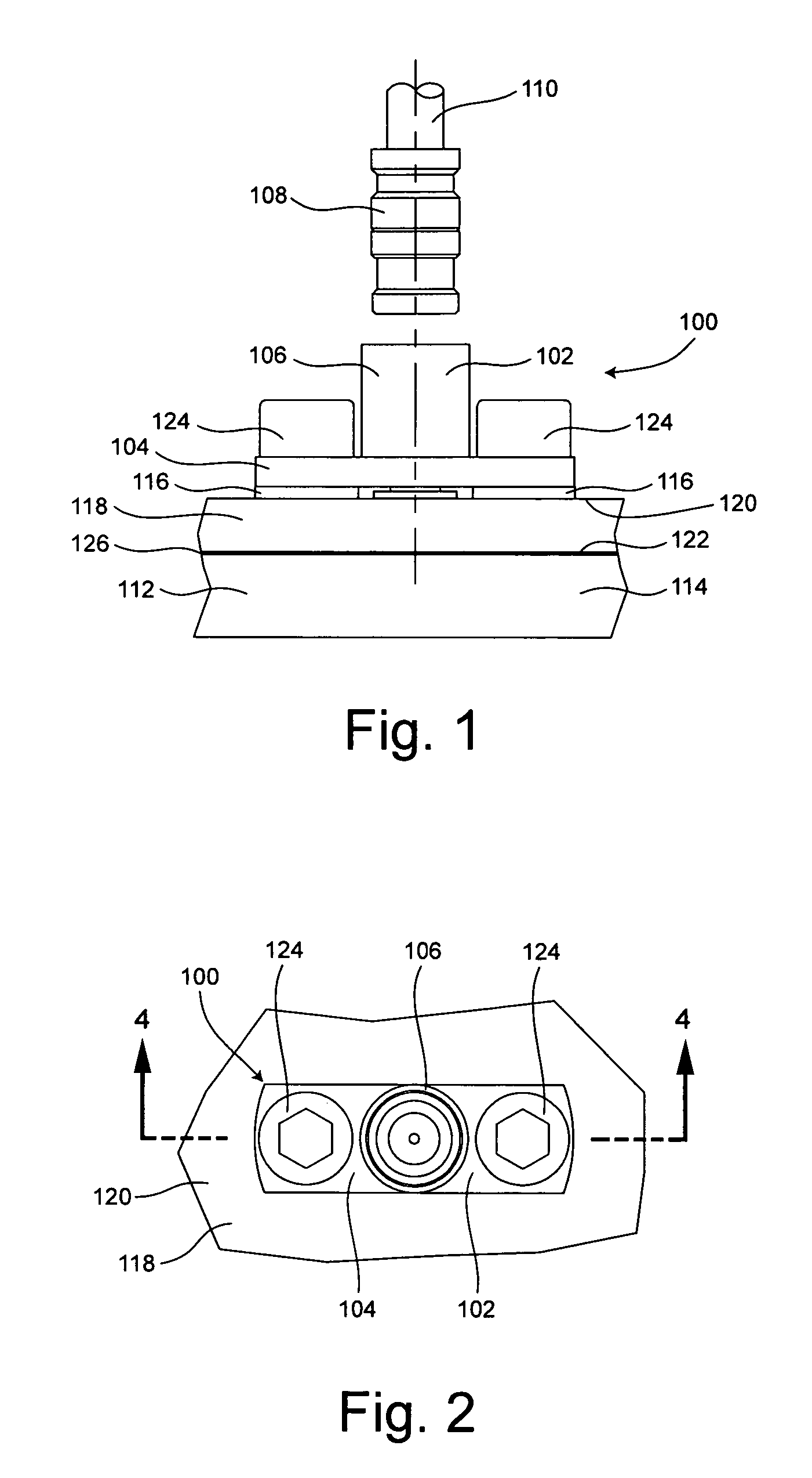
[0015]The present invention relates to a durable coaxial connector (hereinafter “connector”) for providing a reliable signal connection to a printed circuit board (PCB) while isolating the PCB from mechanical loads that are applied to the connector. The present invention also relates to an electrical system which includes such a connector. In addition to having favorable thermal dissipation characteristics, the connector is designed to withstand significant mechanical loads. Accordingly, the connector can prevent damage to the PCB that often occurs from installation and removal of coaxial cables, motion of cables during shock and vibration, and clamping of cables during system assembly.

[0016]FIG. 1 is a side view of a connector 100 which is useful for understanding the present invention. A top view of the connector 100 is shown in FIG. 2. The connector 100 can include an electrically conductive connector body 102 that comprises at least one flange 104 and a connector interface membe...


PUM


Abstract

A durable coaxial connector (100) for providing a reliable signal connection to a printed circuit board (PCB) (118) while isolating the PCB from mechanical loads that are applied to the connector, and an electrical system incorporating the same. The connector can include a connector body (102) having a connector interface member (106), at least one flange (104), and a ground interface member (304) having a first portion (306) configured to be fixedly attached to the PCB and a second portion (308) configured to slideably mate to a ground interface receptacle defined in the connector body. A connector interface can be defined on an inner surface (410) of the connector interface member. A fastener (124) can couple the connector body to a heat sink (112). A thermally conductive boss (116) can be provided to mount the connector body (102) and transfer thermal energy from the connector body to the heat sink.

Description

BACKGROUND OF THE INVENTION[0001]1. Statement of the Technical Field[0002]The inventive arrangements relate to coaxial connectors and, more particularly, to a coaxial connector for providing a signal connection to a printed circuit board.[0003]2. Description of the Related Art[0004]When assembling electrical systems it is often necessary to connect a coaxial cable to a printed circuit board (PCB) for propagation of high frequency signals to or from the PCB. Surface mount coaxial connectors are conventionally used to establish a reliable signal connection between the coaxial cable and the PCB. For example, male and female surface mount coaxial connectors are currently available in various configurations. The current state of the art connectors are not ideal, however, because such connectors are not designed to withstand significant mechanical loads. Consequently, PCBs are oftentimes damaged due to installation and removal of coaxial cables, motion of cables during shock and vibration...

Claims


Application Information

Patent Timeline
Patent Type & Authority Patents(United States)
IPC IPC(8): H05K1/00H01R24/38
CPCH01R13/6315H01R24/50H01R13/6592H01R13/6583H01R9/0515H01R13/6585H01R2103/00
Inventor CLARK, WILLIAM E.SARTIN, JOEY D.
Owner NORTH SOUTH HLDG
Learn More