
Footswitch

a technology of footswitch and foot, which is applied in the field of footswitch, can solve the problems of improper control input, over-complex footswitch, and the potential of injuring patients, and achieve the effect of reducing the fatigue of the user's foo

Active Publication Date: 2006-03-28
ALCON INC
View PDF41 Cites 58 Cited by
  • Summary
  • Abstract
  • Description
  • Claims
  • Application Information

AI Technical Summary

Benefits of technology

[0007]In another aspect, the present invention is a footswitch including a base assembly, a side switch mounted on the base assembly for providing a first control output; and a pivotable treadle mounted on the base assembly for providing a second control output. The treadle has a top surface and a plate on the top surface. The plate is slidably disposed along a linear path relative to the top surface so as to facilitate actuation of the side switch by the user's foot.
[0008]The present invention minimizes fatigue of the user's foot or leg and helps to insure proper use of the footswitch.

Problems solved by technology

However, given the ever-increasing complexity of patient treatment apparatus, there remains a need in the art to provide additional control features on a footswitch; while, at the same time, not making the footswitch overly complex.
In addition, there is a need to assure that the footswitch is ergonomically sound to minimize fatigue of the user's foot or leg, as such fatigue may cause improper control inputs.
Such improper control inputs have the potential of injuring a patient.

Method used


Image

  • Footswitch
  • Footswitch
  • Footswitch

Examples


Embodiment Construction

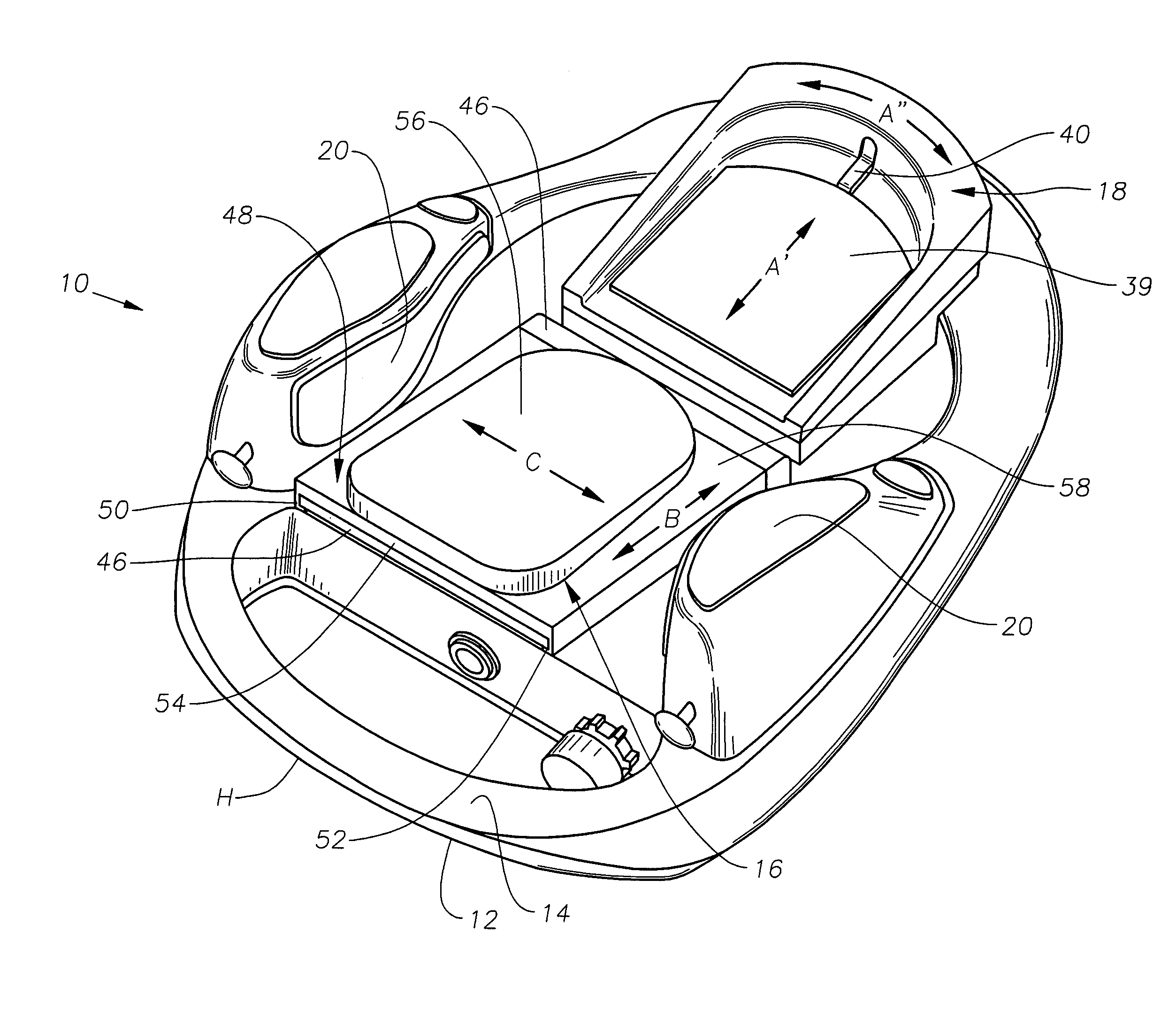
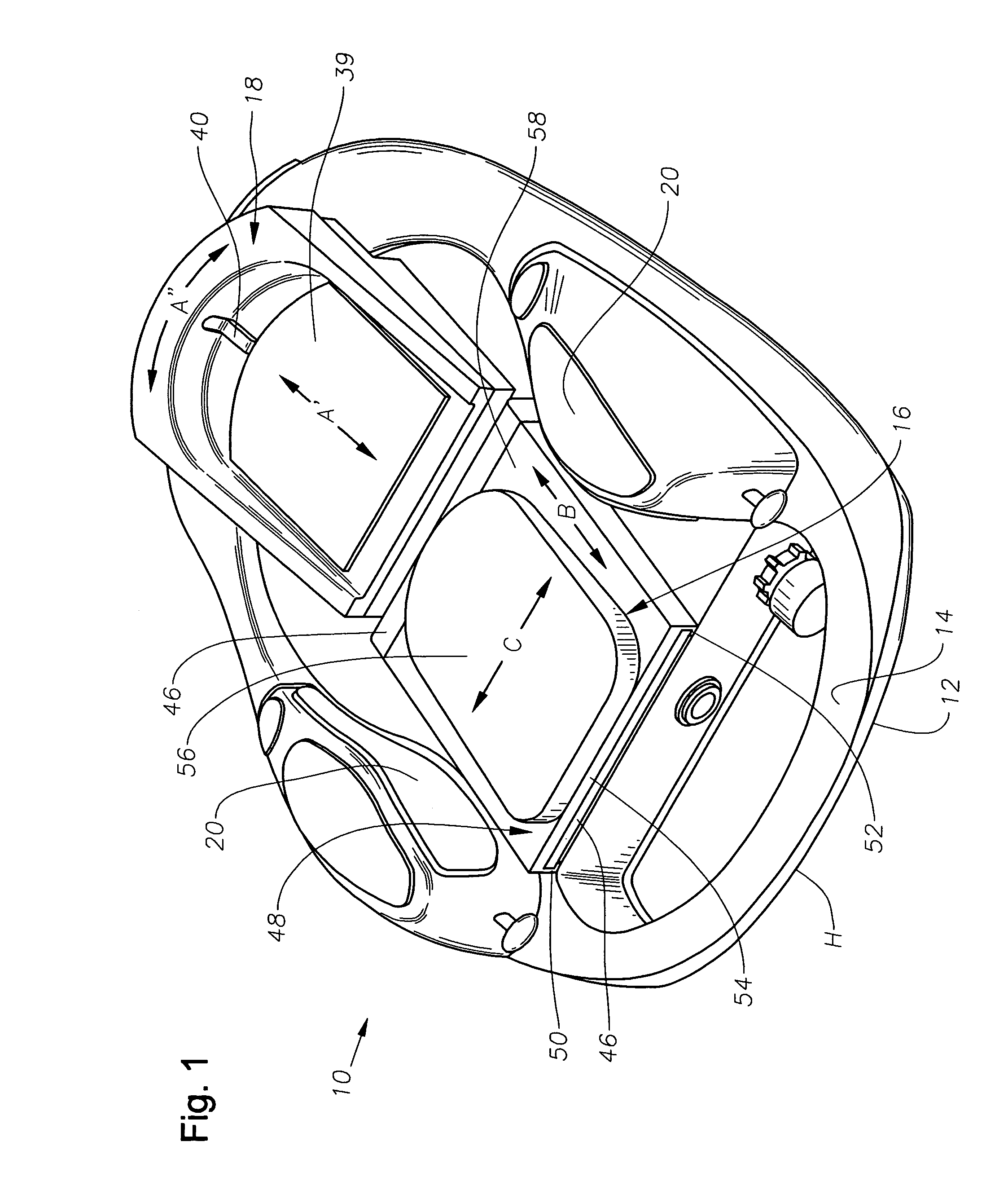
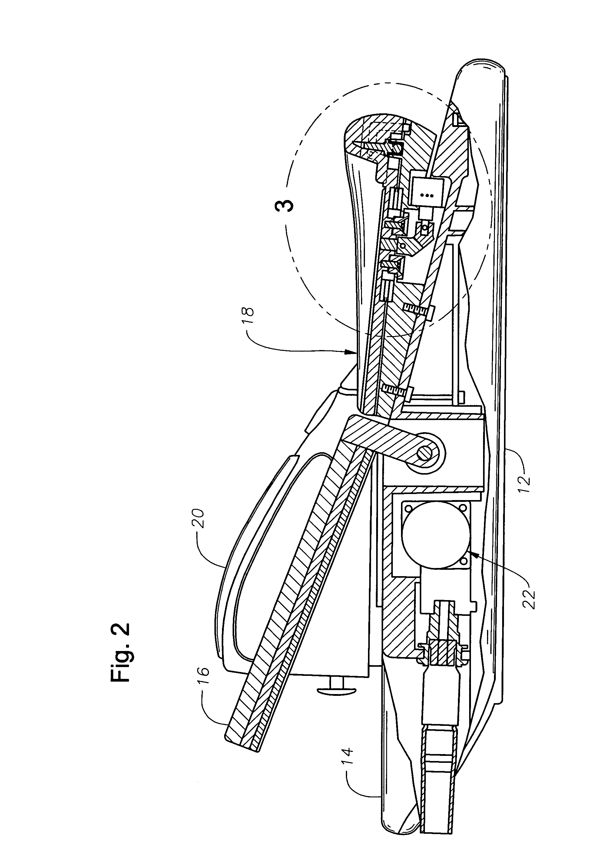
[0013]The preferred embodiments of the present invention and their advantages are best understood by referring to FIGS. 1 through 3 of the drawings, like numerals being used for like and corresponding parts of the various drawings.

[0014]As best seen in FIG. 1 and FIG. 2, a preferred embodiment of the footswitch assembly 10 of the present invention generally includes a bottom housing 12, a top housing 14, a foot pedal or tiltable treadle 16, a separate heel cup assembly 18, a handle position H in the front, and side or wing switches 20.

[0015]Attached to the foot pedal or tiltable treadle 16 is a DC motor / encoder 22. The angular position of the foot pedal or treadle 16, which is tiltable with respect to a horizontal plane or to a neutral or home plane, provides the first system for converting of mechanical input from movement of the user's foot into an electrical signal. Thus, the movement of the foot pedal or tiltable treadle 16 provides a proportional control input, which is prefera...


PUM


Abstract

An improved footswitch is disclosed. The footswitch may have an adjustable length treadle to accommodate different size feet. The footswitch may also have a treadle having a slidable plate that facilitates the actuation of a side switch.

Description

[0001]This application claims the priority of U.S. Provisional Application No. 60 / 520,381 filed Nov. 13, 2003.FIELD OF THE INVENTION[0002]This invention relates to the field of footswitches; more particularly to footswitches used to control patient treatment apparatus used by physicians, surgeons, dentists, veterinarians, etc.DESCRIPTION OF THE RELATED ART[0003]During the use of a complex patient treatment apparatus; for example, the handpiece used when performing ophthalmic surgery, the control of a variety of different subsystems such as pneumatic and electronically driven sub-systems is required. Typically, the operation of the sub-systems included in a complex patient treatment apparatus is controlled by a microprocessor-driven console that receives mechanical inputs from either the user of the device or from an assistant. A control device, generically known as a footswitch, is often used for receiving the mechanical inputs which originate from the movement of the foot of a user...

Claims


Application Information

Patent Timeline
IPC IPC(8): H01H3/14
CPCH01H3/14
Inventor MEZHINSKY, VICTOR B.HOPKINS, MARK A.
Owner ALCON INC
Features
  • Generate Ideas
  • Intellectual Property
  • Life Sciences
  • Materials
  • Tech Scout
  • Unparalleled Data Quality
  • Higher Quality Content
  • 60% Fewer Hallucinations
Learn More