
Green light-emitting microcavity OLED device using a yellow color filter element

a microcavity and filter element technology, applied in the direction of discharge tube luminescnet screens, natural mineral layered products, etc., can solve the problem of color change of emission, and achieve the effect of reducing the color change when viewed at various angles relative to the substrate and reducing the luminan

Active Publication Date: 2006-03-28
GLOBAL OLED TECH
View PDF17 Cites 76 Cited by
  • Summary
  • Abstract
  • Description
  • Claims
  • Application Information

AI Technical Summary

Benefits of technology

The solution significantly reduces color variation when viewed at various angles and maintains minimal luminance loss in green light emission, ensuring consistent green color perception.

Problems solved by technology

However, devices constructed with microcavities suffer from the problem that when viewed at various angles, the color of the emission can change.

Method used


Image

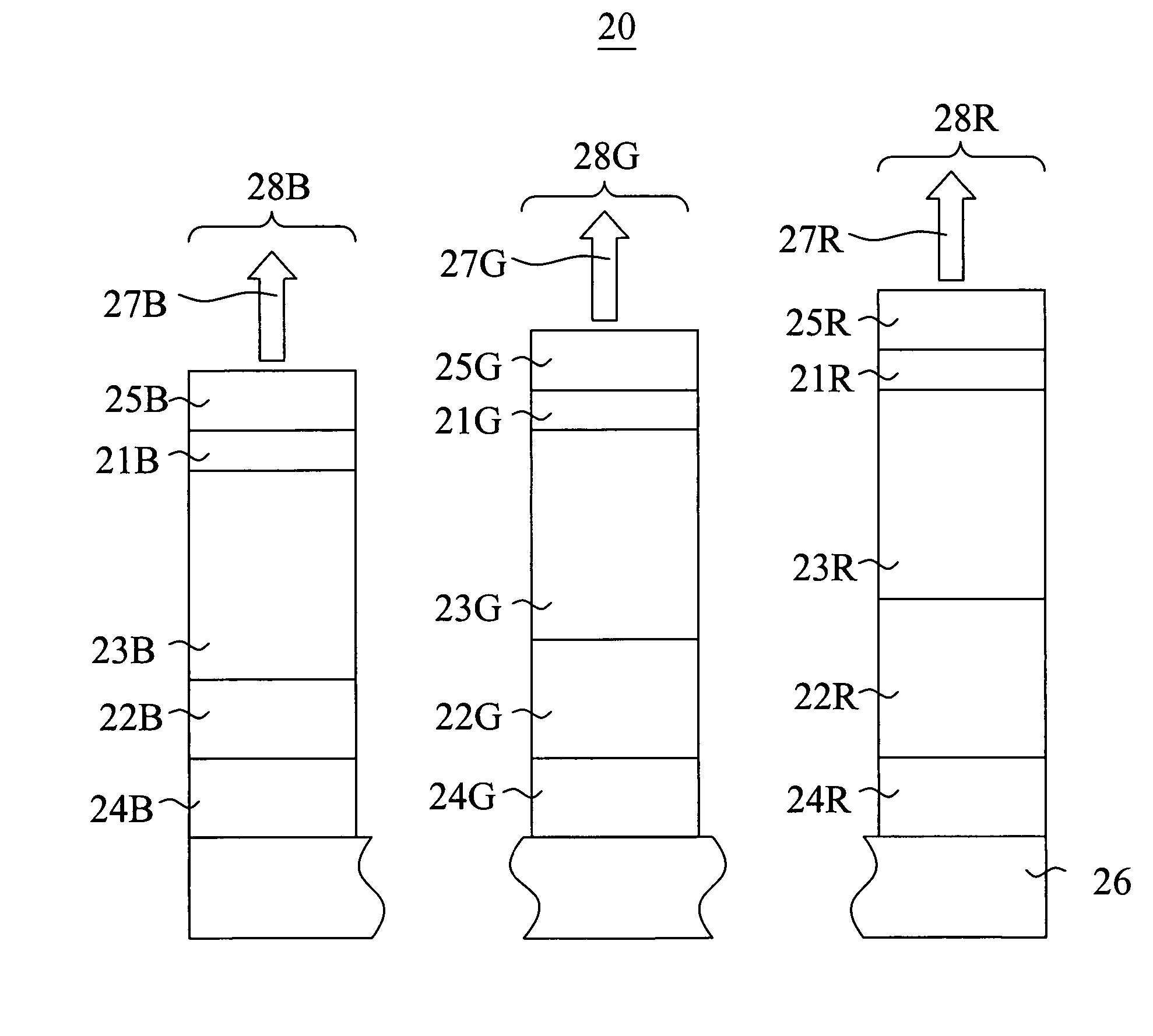
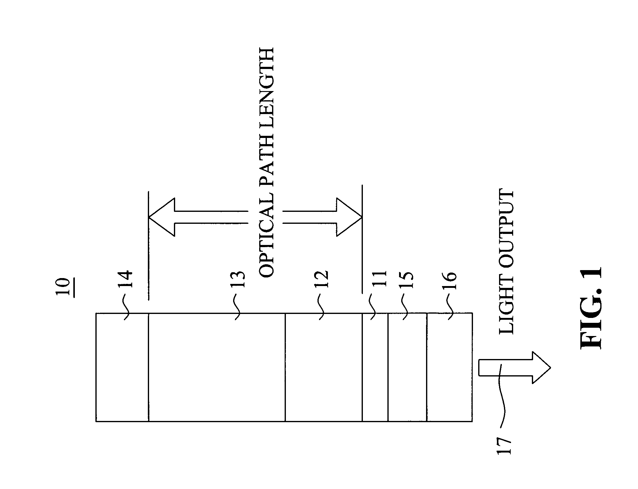
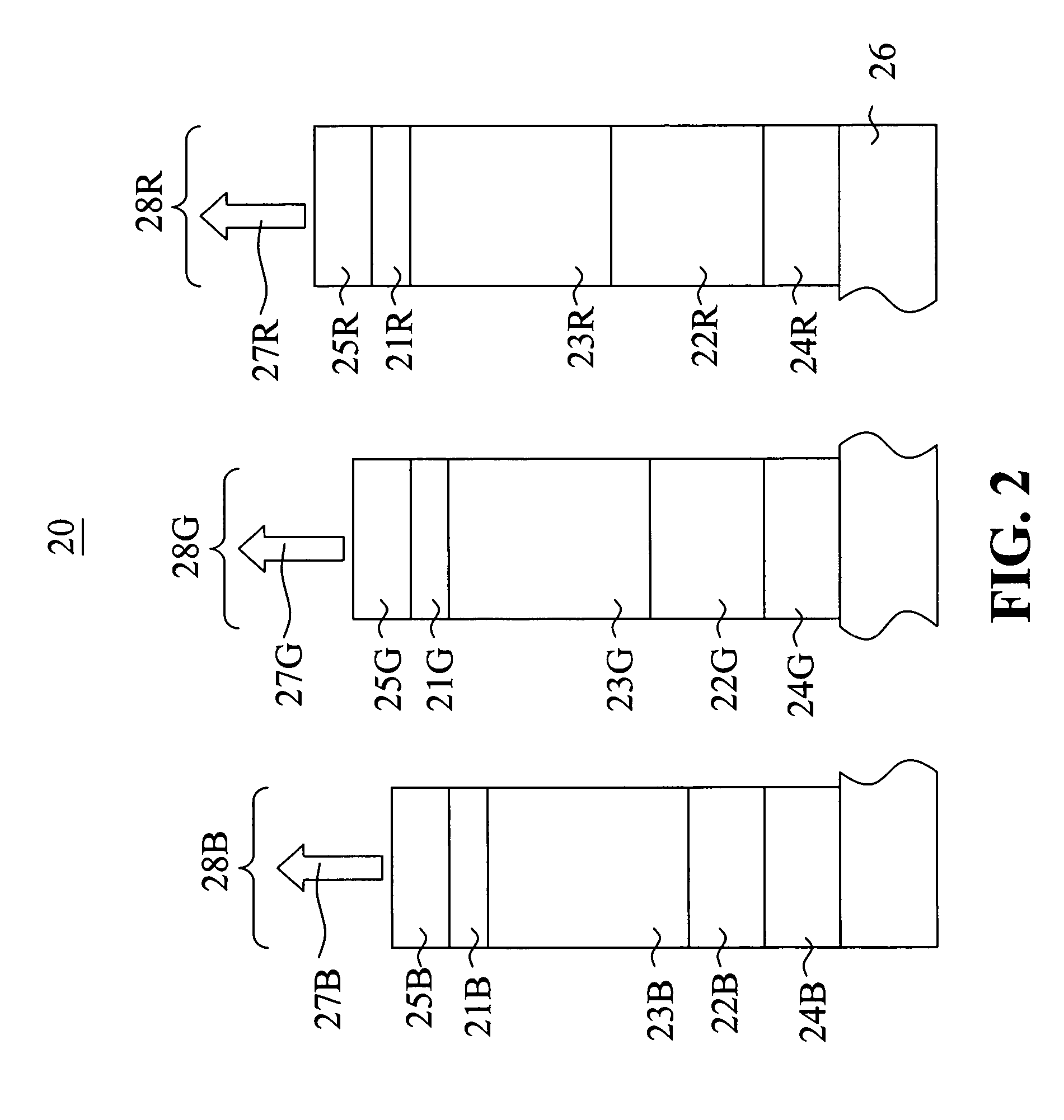
  • Green light-emitting microcavity OLED device using a yellow color filter element
  • Green light-emitting microcavity OLED device using a yellow color filter element
  • Green light-emitting microcavity OLED device using a yellow color filter element

Examples


example

[0036]The present invention is explained more specifically with reference to the following example.

[0037]A microcavity device (Device 1) was prepared having a configuration as follows: a transparent glass substrate; a 20 nm Ag semitransparent reflector; a 100 nm Al reflector; a plurality of organic layers with a refractive index of approximately 1.8; and no cavity spacer layer. The total thickness of the organic layers was 254 nm. This thickness was selected so as to produce a microcavity structure approximately optimized to enhance emission in the green wavelengths. A filter was not added directly to this device so that the unfiltered emission could be measured. The emission after the filter was then calculated by multiplying (cascading) the known transmission properties a color filter element to the unfiltered emission of the microcavity device.

[0038]FIG. 3 shows the emission properties of the microcavity device (Device 1) without a color filter element at viewing angles of 0 degr...


PUM

PropertyMeasurementUnit
cut-off wavelengthaaaaaaaaaa

Abstract

An OLED device having green emitting regions disposed over a substrate, and wherein each green emitting region includes one or more light-emitting layer(s), a reflector and a semitransparent reflector respectively disposed on opposite sides of the light-emitting layer(s) and arranged to resonate light produced by such layers such that the light has a substantial green spectral component, and a yellow color filter element disposed in relationship to each green emitting region to produce green light.

Description

FIELD OF INVENTION[0001]This invention relates to microcavity organic electroluminescent (EL) devices.BACKGROUND OF THE INVENTION[0002]Full color organic electroluminescent (EL), also known as organic light-emitting devices or OLED, have recently been demonstrated as a new type of flat panel display. In simplest form, an organic EL device is comprised of an electrode serving as the anode for hole injection, an electrode serving as the cathode for electron injection, and an organic EL medium sandwiched between these electrodes to support charge recombination that yields emission of light. An example of an organic EL device is described in commonly assigned U.S. Pat. No. 4,356,429. In order to construct a pixilated display device such as is useful, for example, as a television, computer monitor, cell phone display or digital camera display, individual organic EL elements can be arranged as an array of pixels in a matrix pattern. To produce a multicolor display, the pixels are further ...

Claims


Application Information

Patent Timeline
Patent Type & Authority Patents(United States)
IPC IPC(8): H01L27/15H01J1/62H01L27/32H01L51/52
CPCH01L27/322H01L51/5265Y10S428/917H10K59/38H10K59/876H10K50/852
Inventor WINTERS, DUSTINALESSI, PAULA J.BOROSON, MICHAEL L.TYAN, YUAN-SHENG
Owner GLOBAL OLED TECH
Learn More