Current-in-plane magnetic sensor including a trilayer structure

Inactive Publication Date: 2006-03-28
SEAGATE TECH LLC
View PDF20 Cites 40 Cited by
  • Summary
  • Abstract
  • Description
  • Claims
  • Application Information

AI Technical Summary

Problems solved by technology

There are issues with both of these types of sensors that are delaying them from being incorporated into products.

Method used


Image

  • Current-in-plane magnetic sensor including a trilayer structure
  • Current-in-plane magnetic sensor including a trilayer structure
  • Current-in-plane magnetic sensor including a trilayer structure

Examples


Embodiment Construction

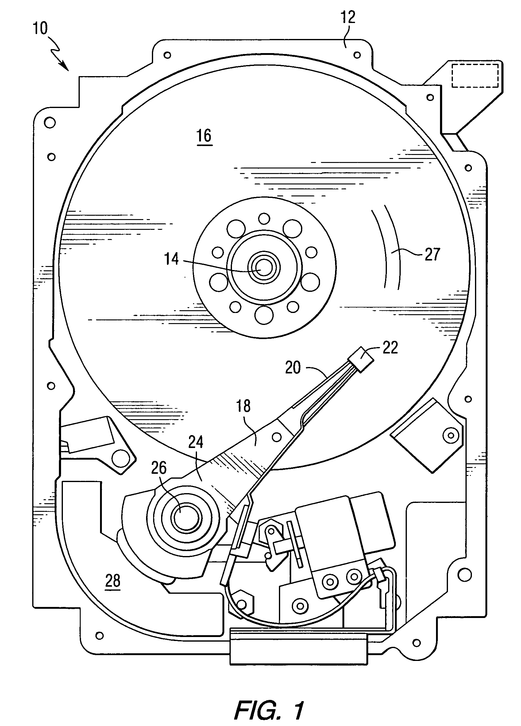
[0034]Referring to the drawings, FIG. 1 is a pictorial representation of a disc drive 10 that can utilize a transducer in accordance with this invention. The disc drive 10 includes a housing 12 (with the upper portion removed and the lower portion visible in this view) sized and configured to contain the various components of the disc drive. The disc drive 10 includes a spindle motor 14 for rotating at least one storage medium 16, which may be a ferroelectric recording medium, within the housing 12. At least one arm 18 is contained within the housing 12, with each arm 18 having a first end 20 with a recording head or slider 22, and a second end 24 pivotally mounted on a shaft by a bearing 26. An actuator motor 28 is located at the arm's second end 24 for pivoting the arm 18 to position the recording head 22 over a desired sector or track 27 of the disc 16. The actuator motor 28 is regulated by a controller, which is not shown in this view and is well-known in the art.

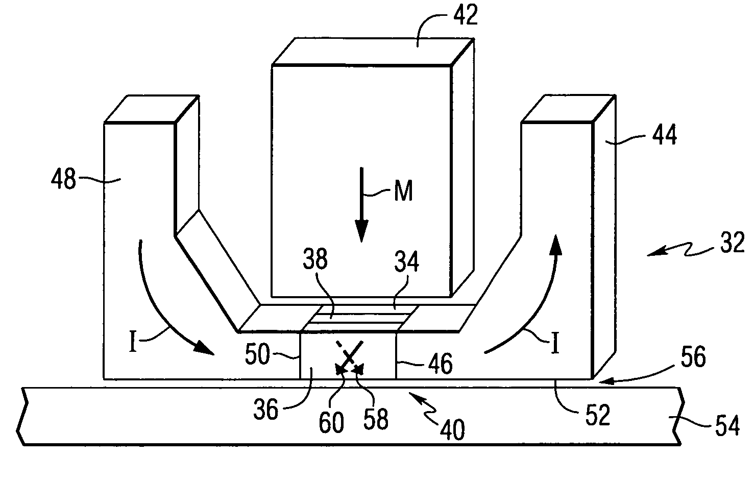
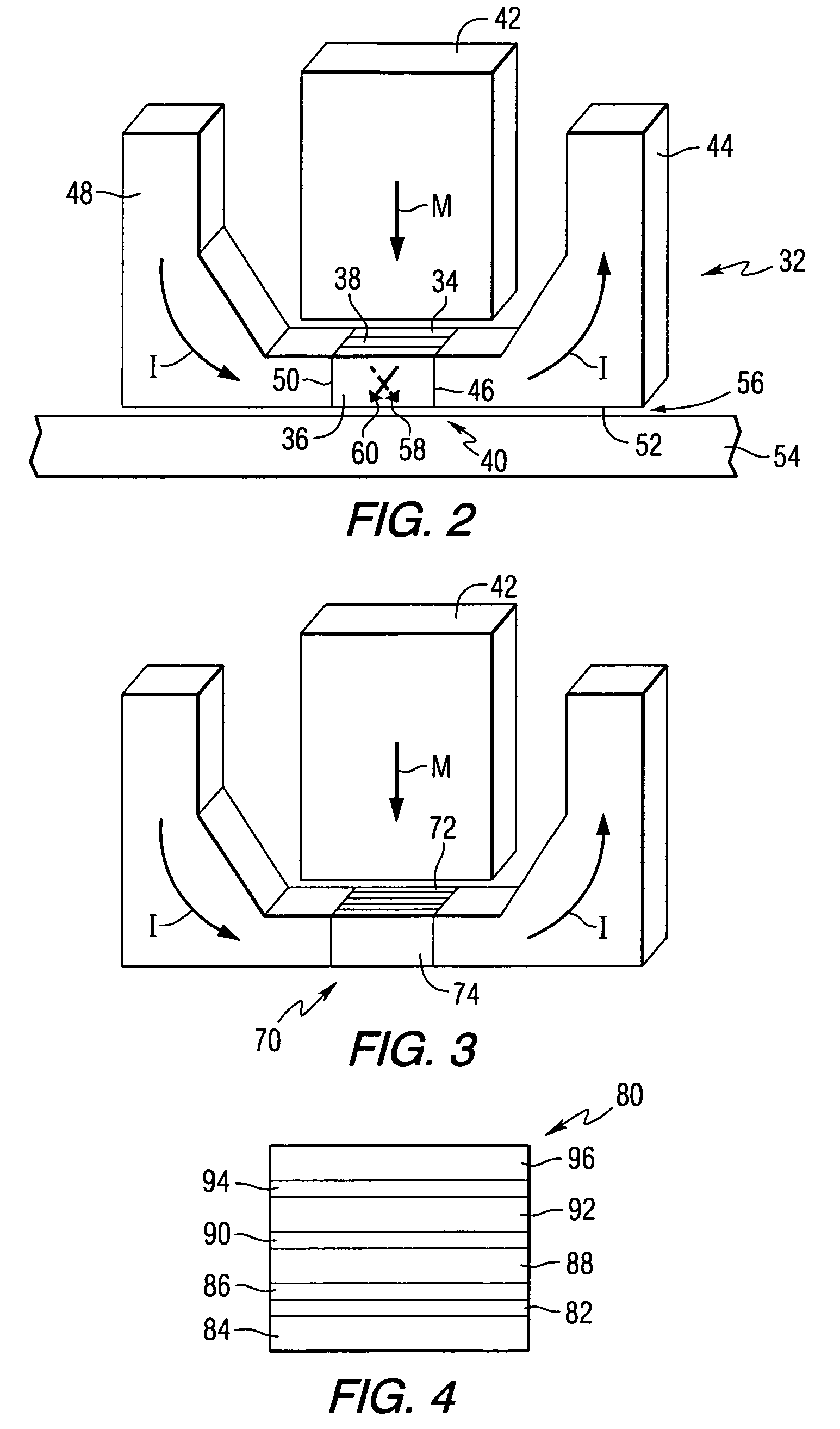
[0035]FIG. 2 is...


PUM

PropertyMeasurementUnit
thicknessaaaaaaaaaa
magnetic fieldaaaaaaaaaa
magnetizationaaaaaaaaaa

Abstract

A current-in-plane magnetic sensor comprises a sensor stack including first and second layers of ferromagnetic material, a first nano-oxide layer positioned adjacent to the first layer of ferromagnetic material, and a layer of non-magnetic material positioned between the first and second layers of ferromagnetic material, wherein the thickness of the non-magnetic layer is selected to provide antiferromagnetic coupling between the first and second ferromagnetic layers, a magnetic field source for biasing the directions of magnetization of the first and second layers of ferromagnetic material in directions approximately 90° with respect to each other, a first lead connected to a first end of the sensor stack, and a second lead connected to a second end of the sensor stack. Disc drives that use the current-in-plane magnetic sensor are also included.

Description

FIELD OF THE INVENTION[0001]This invention relates to magnetic sensors, and more particularly to current-in-plane magnetic sensors.BACKGROUND OF THE INVENTION[0002]Current-in-plane spin-valve (CIP-SV) magnetic sensors have been used as read sensors in magnetic disc drives. It has been predicted that the current-in-plane spin-valve (CIP-SV) will not be able to be used in discs having data densities beyond ˜100 Gbpsi. Other read sensor alternatives such as tunneling magnetoresistance sensors and current-perpendicular-to-plane (CPP) giant magnetoresistance sensors are being explored to replace the CIP-SV. There are issues with both of these types of sensors that are delaying them from being incorporated into products. Because of the vast amount of experience with CIP sensors, it would be advantageous to be able to use the CIP sensor in disc drives having data densities beyond 100 Gbpsi.[0003]A general rule of thumb equation that gives the output voltage for a read sensor is ΔV=Ib*DRshe...

Claims


Application Information

Patent Timeline
Patent Type & Authority Patents(United States)
IPC IPC(8): H01L29/82G01R33/09G11B5/33H01L43/08
CPCB82Y25/00G11B5/33G01R33/093H01L43/08H10N50/10
Inventor SEIGLER, MICHAEL ALLEN
Owner SEAGATE TECH LLC
Why Eureka
Try Eureka