
Layer system having an increased magnetoresistive effect and use of the same, wherein a first layer of an artificial antiferromagnet has a relatively low cobalt content

a technology of magnetoresistive effect and layer system, which is applied in the direction of galvano-magnetic amplifiers, magnetic bodies, instruments, etc., can solve the problem of restricting the magnetic matching of the aaf part-system to the remaining parts, and achieves the effect of greater flexibility

Inactive Publication Date: 2005-11-29
SIEMENS AG
View PDF2 Cites 32 Cited by
  • Summary
  • Abstract
  • Description
  • Claims
  • Application Information

AI Technical Summary

Benefits of technology

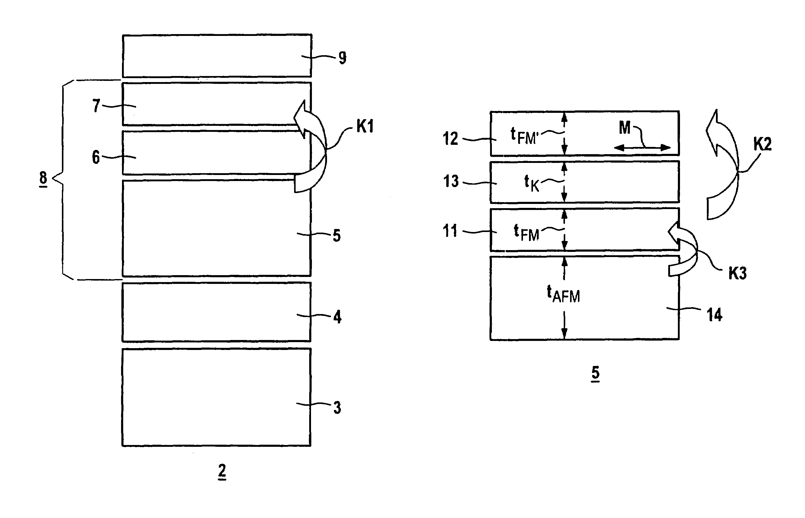
"The present invention relates to a layer system that allows for greater flexibility in matching its AAF part-system. The invention achieves this by providing a layer system with a first ferromagnetic layer that is exchange-coupled to an antiferromagnetic additional layer. The first ferromagnetic layer has a different composition than the second ferromagnetic layer and must maintain antiferromagnetic coupling. The layer system has advantages for optimizing the AAF part-system, such as optimizing the indirect exchange coupling, direct antiferromagnetic exchange coupling, magnetic rotation properties, and the Néel coupling. The second ferromagnetic layer is magnetically softer than the first ferromagnetic layer to avoid the formation of undesired 360° walls. The second ferromagnetic layer consists of a CoFe alloy with lower Co content than the first ferromagnetic layer. The antiferromagnetic additional layer is advantageously selected from the group consisting of NiO, FeMn, IrMn, NiMn, TbMn, CrPtMn, RhMn, PtMn, and PdMn. The coupling layer preferably consists of a material selected from the group of noble metals, in particular from the group consisting of Cu, Ag, Au, Pd, and Ru. The layer system can be used in a magnetic field sensor or a magneto coupler."

Problems solved by technology

It has been discovered that this restricts the magnetic matching of the AAF part-system to the remaining parts of the layer system.

Method used


Image

  • Layer system having an increased magnetoresistive effect and use of the same, wherein a first layer of an artificial antiferromagnet has a relatively low cobalt content
  • Layer system having an increased magnetoresistive effect and use of the same, wherein a first layer of an artificial antiferromagnet has a relatively low cobalt content

Examples


Embodiment Construction

[0026]The layer system 2 according to the invention, which is shown in section in FIG. 1, is based on known multilayer systems which have an increased magnetoresistive effect ΔR / R. Accordingly, the magnetoresistive effect of this system is greater than that of known magnetoresistive single-layer systems with an anisotropic magnetoresistive effect (“AMR” effect) and in particular is over 2% at room temperature. The layer system is either giant-magnetoresistive (“GMR”) or tunneling-magnetoresistive (“TMR”) or colossal-magnetoresistive (“CMR”) or has a giant magnetoimpedance or a giant AC resistance (“GMI”). The differences between corresponding layer systems are explained, for example, in the volume “XMR-Technologien”—Technologieanalyse: Magnetismus, Vol. 2—of the VDI Technology Center “Physi-kalische Technologien”, Düsseldorf (DE) 1997, pages 11 to 46. In this context, the term “XMR technologies” is used as a collective term for the technical know-how based on the magnetoresistance e...


PUM

PropertyMeasurementUnit
thicknessaaaaaaaaaa
thicknessaaaaaaaaaa
thicknessaaaaaaaaaa

Abstract

The layer system having an increased magnetoresistive effect contains at least one soft magnetic detection layer, a non-magnetic decoupling layer, which rests on the detection layer, and a layer partial system, which is located at a distance due to the decoupling layer, forms an artificial antiferromagnet, and which is decoupled from the detection layer. This partial system comprises a first ferromagnetic and a second ferromagnetic layer. The first ferromagnetic layer should be antiferromagnetically coupled (K2) to the second ferromagnetic layer via a non-magnetic coupling layer. In addition, the side of the first ferromagnetic layer facing away from the coupling layer should be provided with an antiferromagnetic additional layer and be exchange-coupled (K3) thereto and, in addition, should have a material composition that differs from the second ferromagnetic layer.

Description

CROSS REFERENCE TO RELATED APPLICATIONS[0001]This is the 35 USC 371 national stage of international application PCT / DE02 / 02898 filed on 7 Aug. 2002, which designated the United States of America.FIELD OF THE INVENTION[0002]The invention relates to a layer system having an increased magnetoresistive effect, comprising at least one detection layer made from a soft-magnetic material, at least one decoupling layer which bears against the detection layer and is made from a nonmagnetic material, and at least one layer part-system which is spaced apart from the detection layer by the decoupling layer, forms an artificial antiferromagnet and is decoupled from the detection layer. This part-system includes at least one second ferromagnetic layer, which adjoins the decoupling layer, and at least one first ferromagnetic layer, which is antiferromagnetically coupled to the second ferromagnetic layer via a coupling layer made from nonmagnetic material and is provided, on its side facing away fro...

Claims


Application Information

Patent Timeline
Patent Type & Authority Patents(United States)
IPC IPC(8): G01R33/09G11B5/39H01F10/16H01F10/32H01L43/08H01L43/10
CPCB82Y25/00H01F10/3272Y10T428/3183
Inventor BOEVE, HANS
Owner SIEMENS AG
Learn More