Current sensor

a current sensor and sensor technology, applied in the field of current sensors, can solve problems such as deterioration of measurement accuracy, and achieve the effect of high degree of accuracy

Active Publication Date: 2011-09-15
ALPS ALPINE CO LTD
View PDF6 Cites 34 Cited by
  • Summary
  • Abstract
  • Description
  • Claims
  • Application Information

AI Technical Summary

Benefits of technology

[0021]With the present invention, the current sensor includes the magnetic detecting bridge circuit which is constituted of four magneto-resistance effect elements with the resistance value varied by application of the induced magnetic field from the current to be measured, and which has output between two magneto-resistance effect elements. The four magneto-resistance effect elements have the same resistance change rate, and includes the self-pinned type ferromagnetic fixed layer which is formed by anti-ferromagnetically coupling the first ferromagnetic film and the second ferromagnetic film via the antiparallel coupling film therebetween, the nonmagnetic ...

Problems solved by technology

For this reason, there is a problem that the output of the midpoint potential difference is not varied completely in proportion...

Method used


Image

  • Current sensor
  • Current sensor
  • Current sensor

Examples


Embodiment Construction

[0042]Embodiments of the present invention will be now described in detail with reference to the accompanying drawings. First, a case where a current sensor according to the present invention is a magnetic balance current sensor will be described.

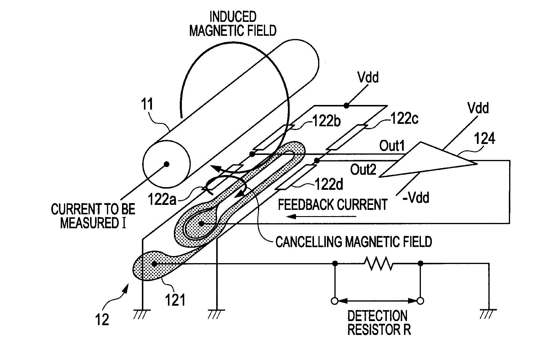
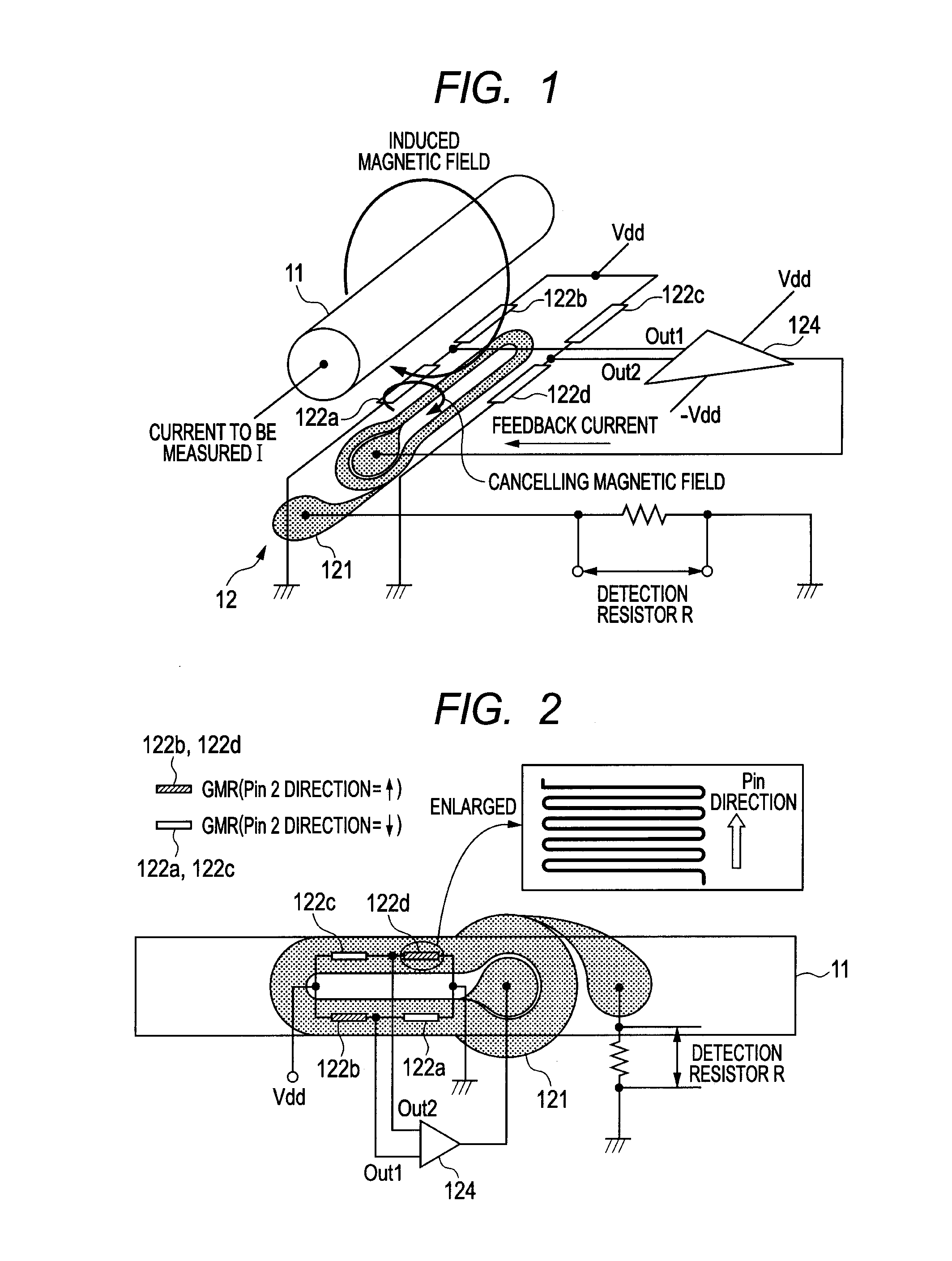
[0043]FIGS. 1 and 2 are diagrams illustrating a magnetic balance current sensor according to an embodiment of the present invention. The magnetic balance current sensor shown in FIGS. 1 and 2 is installed adjacent to a conductor 11 through which a current I to be measured flows. The magnetic balance current sensor includes a feedback circuit 12 for inducing a magnetic field (cancelling magnetic field) for cancelling an induced magnetic field generated from the current I to be measured which flows in the conductor 11. The feedback circuit 12 has a feedback coil 121 wound in a direction for cancelling a magnetic field generated from the current I to be measured, and four magneto-resistance effect elements 122a to 122d.

[0044]The feedback coil...


PUM


Abstract

A current sensor including a magnetic detecting bridge circuit which is constituted of four magneto-resistance effect elements with a resistance value varied by application of an induced magnetic field from a current to be measured, and which has an output between two magneto-resistance effect elements. The four magneto-resistance effect elements have the same resistance change rate, and include a self-pinned type ferromagnetic fixed layer which is formed by anti-ferromagnetically coupling a first ferromagnetic film and a second ferromagnetic film via an antiparallel coupling film therebetween, a nonmagnetic intermediate layer, and a soft magnetic free layer. Magnetization directions of the ferromagnetic fixed layers of the two magneto-resistance effect elements providing the output are different from each other by 180°. The magnetic detecting bridge circuit has wiring symmetrical to a power supply point.

Description

CLAIM OF PRIORITY[0001]This application claims benefit of Japanese Patent Application No. 2010-056154 filed on Mar. 12, 2010, which is hereby incorporated by reference.BACKGROUND OF THE INVENTION[0002]1. Field of the Invention[0003]The present invention relates to a current sensor using a magneto-resistance effect element (TMR element or GMR element).[0004]2. Description of the Related Art[0005]In an electric vehicle, a motor is driven by electricity generated by an engine, and the intensity of the current for driving the motor is detected by, for example, a current sensor. The current sensor includes a magnetic core placed around a conductor and having a cutaway portion (core gap) formed at a portion thereof, and a magnetic detecting element placed in the core gap.[0006]As the magnetic detecting element of the current sensor, a magneto-resistance effect element (GMR element, TMR element) including a laminate structure having a fixed magnetic layer with a fixed magnetizing direction...

Claims


Application Information

Patent Timeline
IPC IPC(8): G01R33/02
CPCG01R15/205G01R33/09G01R19/0092
Inventor ICHINOHE, KENJISAITO, MASAMICHITAKAHASHI, AKIRAIDE, YOSUKE
Owner ALPS ALPINE CO LTD
Why Eureka
Try Eureka