Magnetic device having perpendicular magnetization and interaction compensating interlayer

a technology of perpendicular magnetization and magnetic devices, applied in the field of microstructures having magnetic properties, can solve the problems of increasing the thickness of the layer, the inability of the magnetic layer located either side of the interlayer to be magnetically independent of each other, and the shortening of the stack of magnetic devices

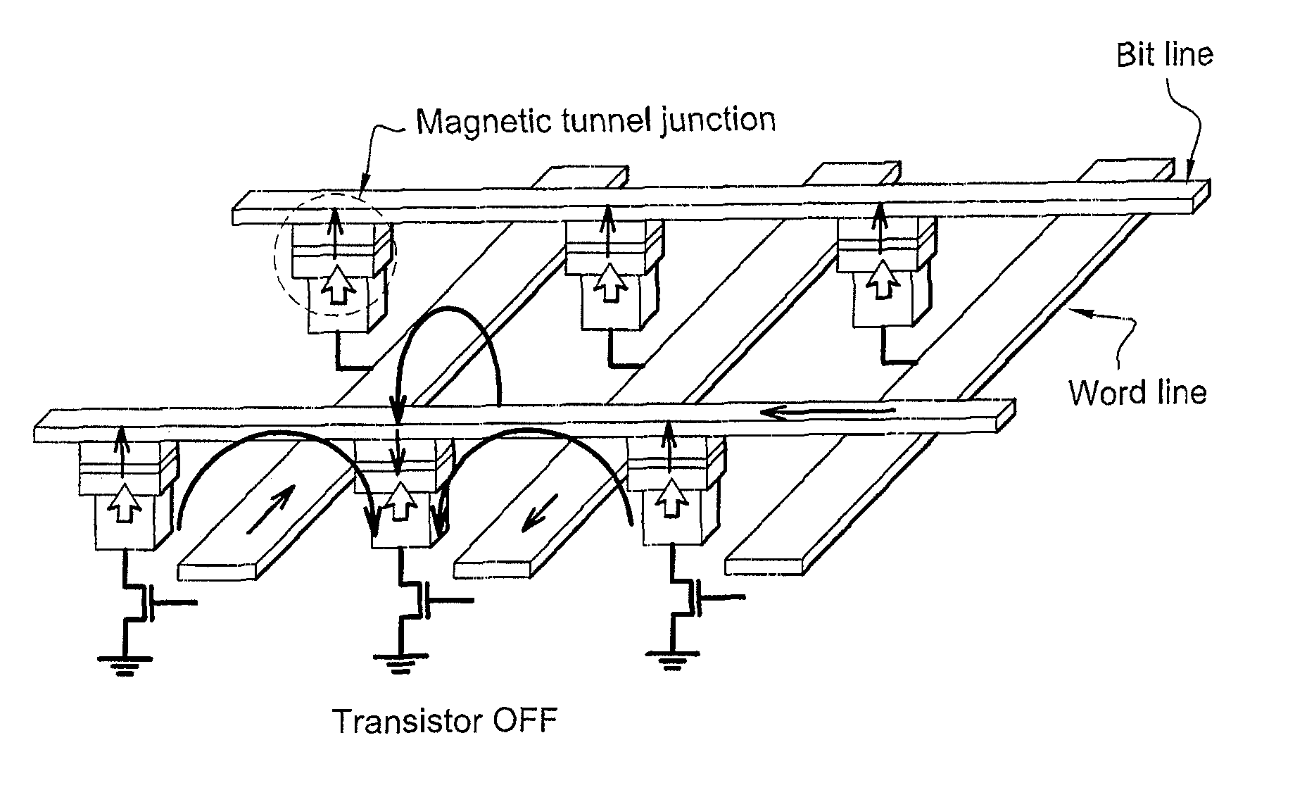
Inactive Publication Date: 2010-08-10
CENT NAT DE LA RECH SCI 15
View PDF9 Cites 33 Cited by
  • Summary
  • Abstract
  • Description
  • Claims
  • Application Information

AI Technical Summary

Benefits of technology

[0063]The term “thickness” is taken to mean the dimension in the direction in which the various layers are stacked, i.e. the direction perpendicular to the plane of the layers. An interlayer structured in this way will encourage antiferromagnetic coupling capable of compensating all or part of the ferromagnetic coupling that occurs between the magnetic layers located either side of such an interlayer.
[0081]Such devices can therefore be extremely compact which allows them to be miniaturized compared to similar devices according to the prior art without their operation being disrupted by magnetostatic fields resulting from such reduction in size or surface roughness of interfaces. In addition, the stable states of the magnetization loops of the magnetic layers have enhanced stability and this makes these devices less sensitive to common magnetic disturbances.

Problems solved by technology

In particular, these layers are becoming increasingly thinner and the stacks that form these magnetic devices are increasingly short and narrow.
Consequently, roughness interaction (orange-peel coupling) and magnetostatic interaction no longer compensate each other but are added to each other, so that the magnetic layers located either side of the interlayer can no longer be made magnetically independent of each other by these two forms of coupling cancelling each other out.
It will nevertheless be possible to access the antiparallel state (high resistance) by means of a magnetic field pulse, but this state will not be maintained once the magnetic field pulse has decayed and non-volatility will be lost.

Method used


Image

  • Magnetic device having perpendicular magnetization and interaction compensating interlayer
  • Magnetic device having perpendicular magnetization and interaction compensating interlayer
  • Magnetic device having perpendicular magnetization and interaction compensating interlayer

Examples


Embodiment Construction

[0091]Among the types of magnetic interactions mentioned above, research has revealed, in particular, a type of coupling that occurs between two thin magnetic layers separated by a non-magnetic metallic interlayer (Systematic variation of the strength and oscillation period of indirect magnetic exchange coupling through the 3d, 4d, and 5d transition metals, S. S. P. Parkin et al, Physical Review Letters 67, 3598-3601 (1991)). This involves RKKY coupling (named after researchers Ruderman, Kittel, Kasuya and Yosida).

[0092]This RKKY coupling is capable of encouraging parallel alignment or antiparallel alignment of the magnetizations of magnetic layers located either side of the interlayer, depending on the nature and the thickness of the latter. The alignment of these magnetizations is determined by the nature of the non-magnetic metallic material and by its thickness, which must nevertheless remain small. In addition, this RKKY coupling is essentially non-dependent on the lateral dime...


PUM


Abstract

The magnetic device comprises a least two layers made of a magnetic material that are separated by at least one interlayer made of a non-magnetic material. The layers made of a magnetic material each have magnetization oriented substantially perpendicular to the plane of the layers. The layer of non-magnetic material induces an antiferromagnetic coupling field between the layers made of a magnetic material, the direction and amplitude of this field attenuating the effects of the ferromagnetic coupling field of magnetostatic origin that occurs between the magnetic layers.

Description

FIELD OF THE INVENTION[0001]The present invention relates to the field of microstructures having magnetic properties. It deals with a magnetic device comprising thin magnetic layers with magnetization perpendicular to the plane of said layers and a non-magnetic interlayer that separates these magnetic layers.[0002]Its potential applications include magnetic memories with multi-coercive fields or magnetic random access memories (MRAM), reprogrammable logic gates, spin valves or magnetic tunnel junctions that incorporate a magnetic device according to the invention.BACKGROUND OF THE INVENTION[0003]The use of magnetic devices comprising at least two layers made of a magnetic material separated by an interlayer made of a non-magnetic material is known in the field of magnetic memories and magnetic recording media. Generally speaking, these various layers and their interfaces are flat and parallel to each other.[0004]In order to enhance the capabilities of such magnetic devices, attempts...

Claims


Application Information

Patent Timeline
Patent Type & Authority Patents(United States)
IPC IPC(8): H01L21/00H01L29/82
CPCG11C11/16G11C11/5607G11C11/1675
Inventor RODMACQ, BERNARDBALTZ, VINCENTBOLLERO, ALBERTODIENY, BERNARD
Owner CENT NAT DE LA RECH SCI 15
Why Eureka
Try Eureka