

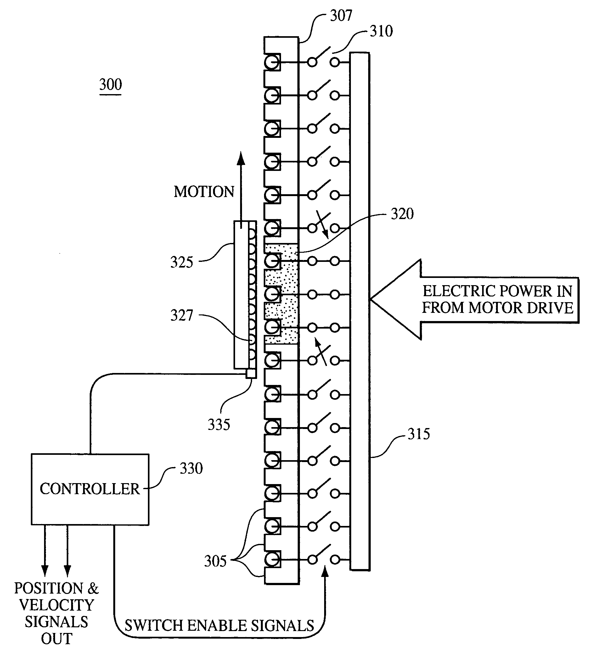
Modular linear electric motor with limited stator excitation zone and stator gap compensation
a technology of linear electric motors and stators, applied in the field of linear motor systems, can solve the problems of inability to use conventional linear motors in these elevator shafts, inability to meet the needs of cabled elevators, so as to reduce the occurrence of door fouling, reduce friction, and reduce the weight of doors
- Summary
- Abstract
- Description
- Claims
- Application Information
AI Technical Summary
Benefits of technology
Problems solved by technology
Method used
Image

Examples
Embodiment Construction
[0023]It is to be understood that the figures and descriptions of the present invention have been simplified to illustrate elements that are relevant for a clear understanding of the invention, while eliminating, for purposes of clarity, other elements that may be well known. Those of ordinary skill in the art will recognize that other elements are desirable and / or required in order to implement the present invention. However, because such elements are well known in the art, and because they do not facilitate a better understanding of the present invention, a discussion of such elements is not provided herein. The detailed description will be provided hereinbelow with reference to the attached drawings.
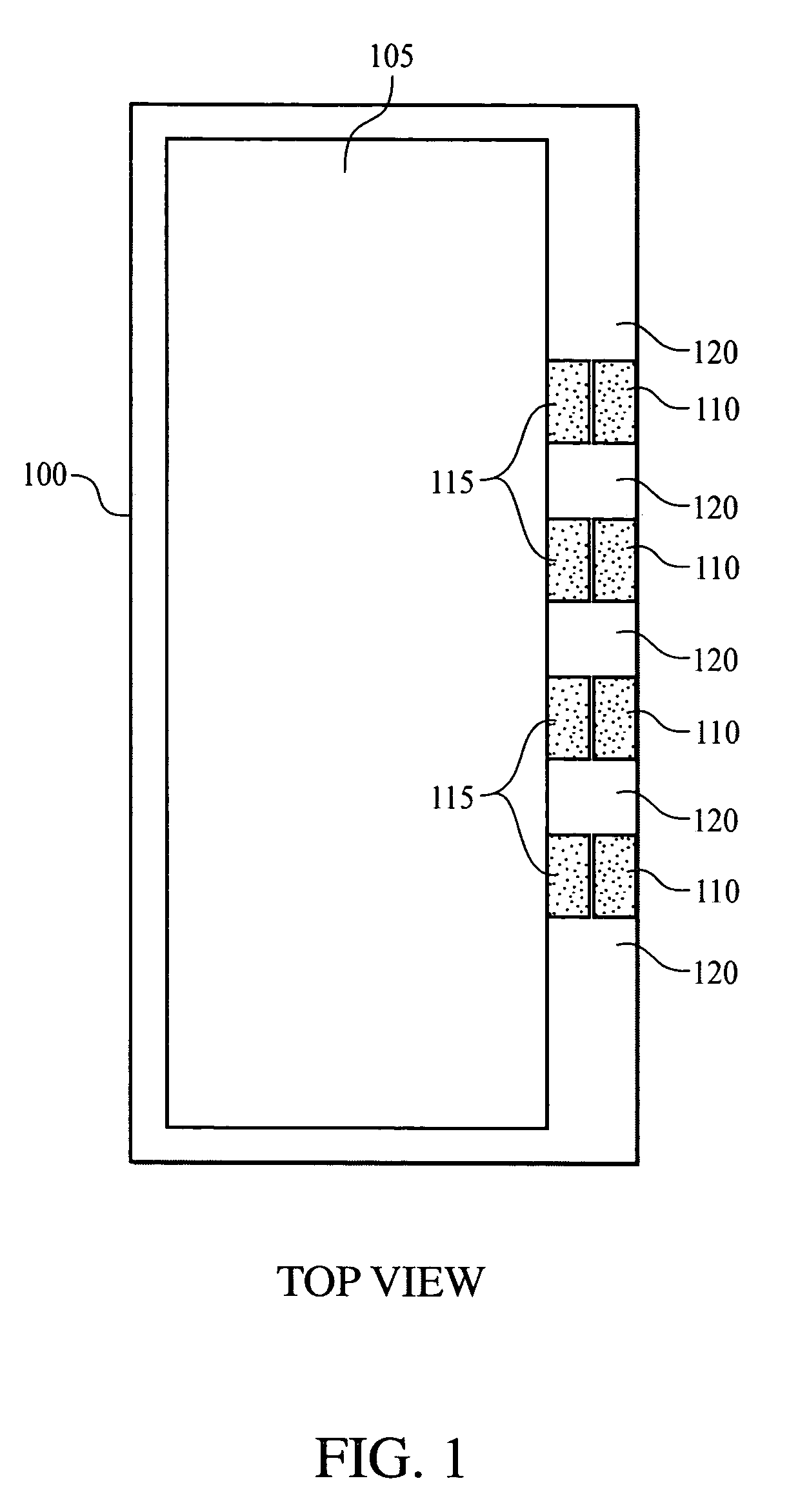
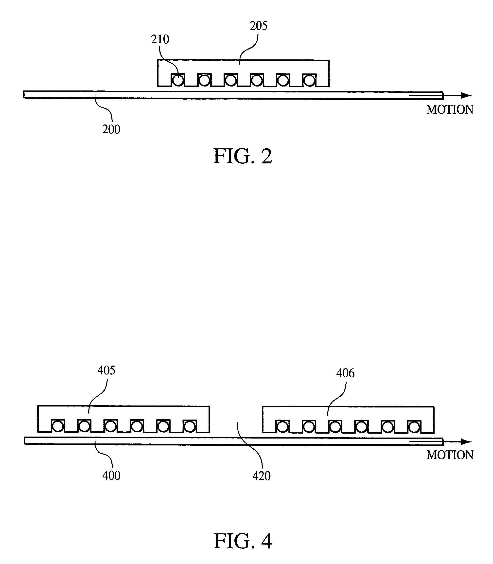
[0024]As briefly described above, linear motors for shipboard weapons (and other) elevator applications must be designed to fit within the confines of the shaft walls. In addition, the linear motor components must not interfere with the necessary elevator guides and supports (see FIG....
PUM
 Abstract
Description
Claims
Application Information