Chucking system for modulating shapes of substrates

a technology of substrates and chucks, applied in the field of lithography systems, can solve the problems of varying the thickness of underlying residual layers, pattern placement errors, line width variations, etc., and achieve the effect of reducing substrate distortions

Inactive Publication Date: 2006-03-28
CANON KK
View PDF147 Cites 78 Cited by
  • Summary
  • Abstract
  • Description
  • Claims
  • Application Information

AI Technical Summary

Benefits of technology

[0001]The field of invention relates generally to lithography systems. More particularly, the present invention is directed to reducing undesirable pattern variations during imprint lithography processes.
[0008]In another embodiment, a pressure control system is included. The first throughway places the first recess in fluid communication with the pressure control system and the second throughway places the pressure control system in fluid communication with the second recess. When mounted to the chuck body, the substrate rests against the first and second support regions, covering the first and second recesses. The first recess and the portion of the substrate in superimposition therewith define a first chamber and the second recess and the portion of the substrate in superimposition therewith defines a second chamber. The pressure control system operates to control a pressure in the first and second chambers. Specifically, the pressure is established in the first chamber to maintain the position of the substrate with the chuck body. The pressure in the second chamber may differ from the pressure in the first chamber to, inter alia, reduce distortions in the substrate that occur during imprinting. These and other embodiments of the present invention are discussed more fully below.

Problems solved by technology

For example, in-plane distortion can cause line width variations, as well as pattern placement errors.
Out-of-plane distortion can cause loss of focus in optical lithography resulting in varying the thickness of underlying residual layers.
This may make difficult both line width control and etch transfer.

Method used


Image

  • Chucking system for modulating shapes of substrates
  • Chucking system for modulating shapes of substrates
  • Chucking system for modulating shapes of substrates

Examples


Embodiment Construction

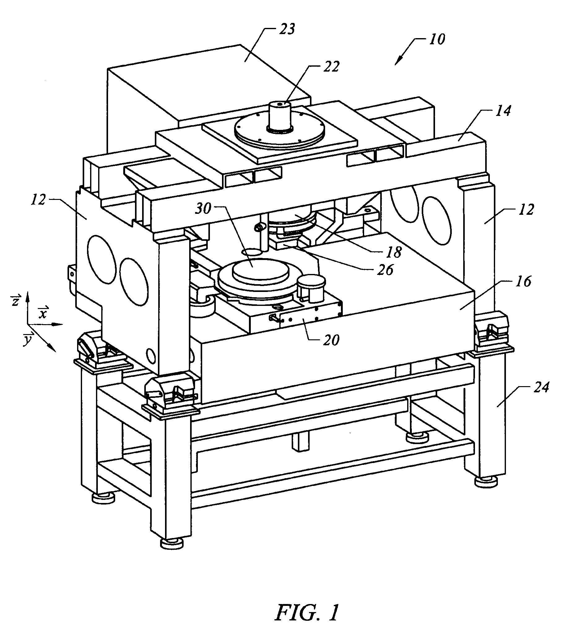
[0025]FIG. 1 depicts a lithographic system 10 in accordance with one embodiment of the present invention that includes a pair of spaced-apart bridge supports 12 having a bridge 14 and a stage support 16 extending therebetween. Bridge 14 and stage support 16 are spaced-apart. Coupled to bridge 14 is an imprint head 18, which extends from bridge 14 toward stage support 16. Disposed upon stage support 16 to face imprint head 18 is a motion stage 20. Motion stage 20 is configured to move with respect to stage support 16 along X and Y axes. A radiation source 22 is coupled to system 10 to impinge actinic radiation upon motion stage 20. As shown, radiation source 22 is coupled to bridge 14 and includes a power generator 23 connected to radiation source 22.

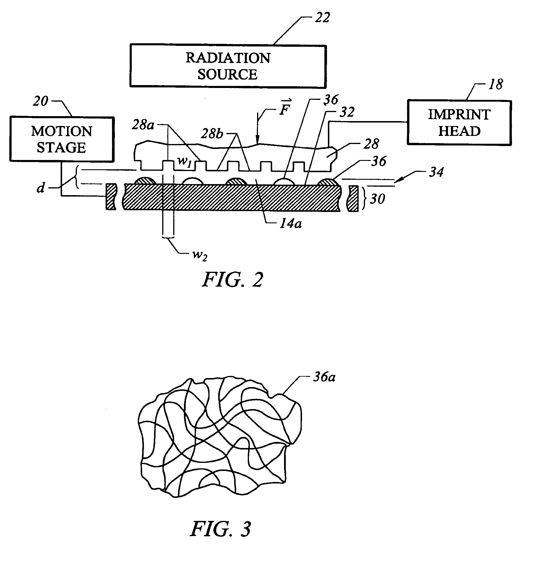
[0026]Referring to both FIGS. 1 and 2, connected to imprint head 18 is a substrate 26 having a mold 28 thereon. Mold 28 includes a plurality of features defined by a plurality of spaced-apart recessions 28a and protrusions 28b. The plura...


PUM

PropertyMeasurementUnit
temperatureaaaaaaaaaa
transparentaaaaaaaaaa
wavelengthaaaaaaaaaa

Abstract

The present invention is directed to a chucking system to modulate substrates so as to properly shape and position the same with respect to a wafer upon which a pattern is to be formed with the substrate. The chucking system includes a chuck body having first and second opposed sides. A side surface extends therebetween. The first side includes first and second spaced-apart recesses defining first and second spaced-apart support regions. The first support region cinctures the second support region and the first and second recesses. The second support region cinctures the second recess, with a portion of the body in superimposition with the second recess being transparent to radiation having a predetermined wavelength. The second side and the side surface define exterior surfaces. The body includes throughways placing the first and second recesses in fluid communication with one of the exterior surfaces.

Description

[0001]The field of invention relates generally to lithography systems. More particularly, the present invention is directed to reducing undesirable pattern variations during imprint lithography processes.[0002]Micro-fabrication involves the fabrication of very small structures, e.g., having features on the order of micro-meters or smaller. One area in which micro-fabrication has had a sizeable impact is in the processing of integrated circuits. As the semiconductor processing industry continues to strive for larger production yields while increasing the circuits per unit area formed on a substrate, micro-fabrication becomes increasingly important. Micro-fabrication provides greater process control while allowing increased reduction of the minimum feature dimension of the structures formed. Other areas of development in which micro-fabrication has been employed include biotechnology, optical technology, mechanical systems and the like.[0003]An exemplary micro-fabrication technique is...

Claims


Application Information

Patent Timeline
Patent Type & Authority Patents(United States)
IPC IPC(8): G03B27/62G03B27/42G03B27/60H01L21/4763G03F7/20
CPCB29C43/003B29C43/021B29C43/36G03F7/70875B29D11/00365G03B27/62G03F7/707B29C33/20B29C43/58B29C2043/025B29C2043/3488B29C2043/5841B29C2043/3233
Inventor CHOI, BYUNG J.VOISIN, RONALD D.SREENIVASAN, SIDLGATA V.WATTS, MICHAEL P. C.BABBS, DANIELMEISSL, MARIO J.BAILEY, HILLMANSCHUMAKER, NORMAN E.
Owner CANON KK
Why Eureka
Try Eureka