Forming fabric

a technology of fabric and web, applied in the field of fabric, can solve the problems of limiting delamination resistance and undesirable basis weight variation in the sheet, and achieve the effects of reducing undesirable basis weight variation, stiffening the composite fabric, and reducing the possibility of forming a recessed area in the paper side fabric surfa

Inactive Publication Date: 2005-05-19
VOITH PATENT GMBH
View PDF15 Cites 50 Cited by
  • Summary
  • Abstract
  • Description
  • Claims
  • Application Information

AI Technical Summary

Benefits of technology

[0018] A forming fabric with the above mentioned features has the following advantage: The pull down force acting on a paper side warp yarn interlacing with a binder weft yarn, according to the above mentioned embodiment, is reduced, because the binder weft yarn floats between at least two consecutive pairs of paper side and wear side warp yarns before traveling from the paper side to the wear side or vice versa. Thus the probability of forming a recessed area in the paper side fabric surface, into which a fiber can penetrate more deeply than surrounding areas, is reduced. As such, undesirable basis weight variation, which may occur in the sheet, is also reduced.
[0019] Furthermore, according to another embodiment of the present invention, a fabric stiffening binder weft section exists when the binder weft yarn, floating between the paper side and wear side fabric layers, beneath at least two consecutive paper side warp yarns, is bound at one end by interlacing with a warp yarn in the paper side layer and is also bound at the other end by interlacing with a warp yarn in the same paper side fabric layer to thereby stiffen the composite fabric. A fabric stiffening binder weft section also exists when a relatively straight length of yarn is bound at each end by a warp yarn of the wear side layer. The triple layer fabrics of the invention are thus stable and have good cross machine direction (CD) bending stiffness with which to control sheet profiles.
[0020] According to a further embodiment of the present invention, the forming fabric has at least one paper side weft yarn positioned adjacent to a binder group. The paper side weft yarn floats under at least two consecutive paper side warp yarns and at least one of the binder weft yarns of the binder group forms a knuckle over one of the at least two consecutive warp yarns. A further embodiment of the present invention is characterized in that the paper side weft yarn floats between at least two consecutive pairs of paper side and wear side warp yarns. By providing such a structure, combined with a binder group that is positioned adjacent to the paper side weft yarn, the binder weft yarns form a knuckle over one of the two consecutive paper side warp yarns. A fabric stiffening top weft section is provided, with which to enhance fabric CD stability, while the binder yarn continues the paper side weave sequence otherwise provided for by the paper side weft yarn.

Problems solved by technology

Because of the practical limitations in the frequency of bindings, between the binder yarns and the warp yarns of the paper side and wear side layers of composite structures with only a single binder yarn, there is a limit to the delamination resistance.
Further, in this structure the binder yarns change from weaving above a paper side warp, to weaving below a wear side warp within the space of several warp yarns, such that undesirable basis weight variation may occur in the sheet.

Method used


Image

  • Forming fabric
  • Forming fabric
  • Forming fabric

Examples


Embodiment Construction

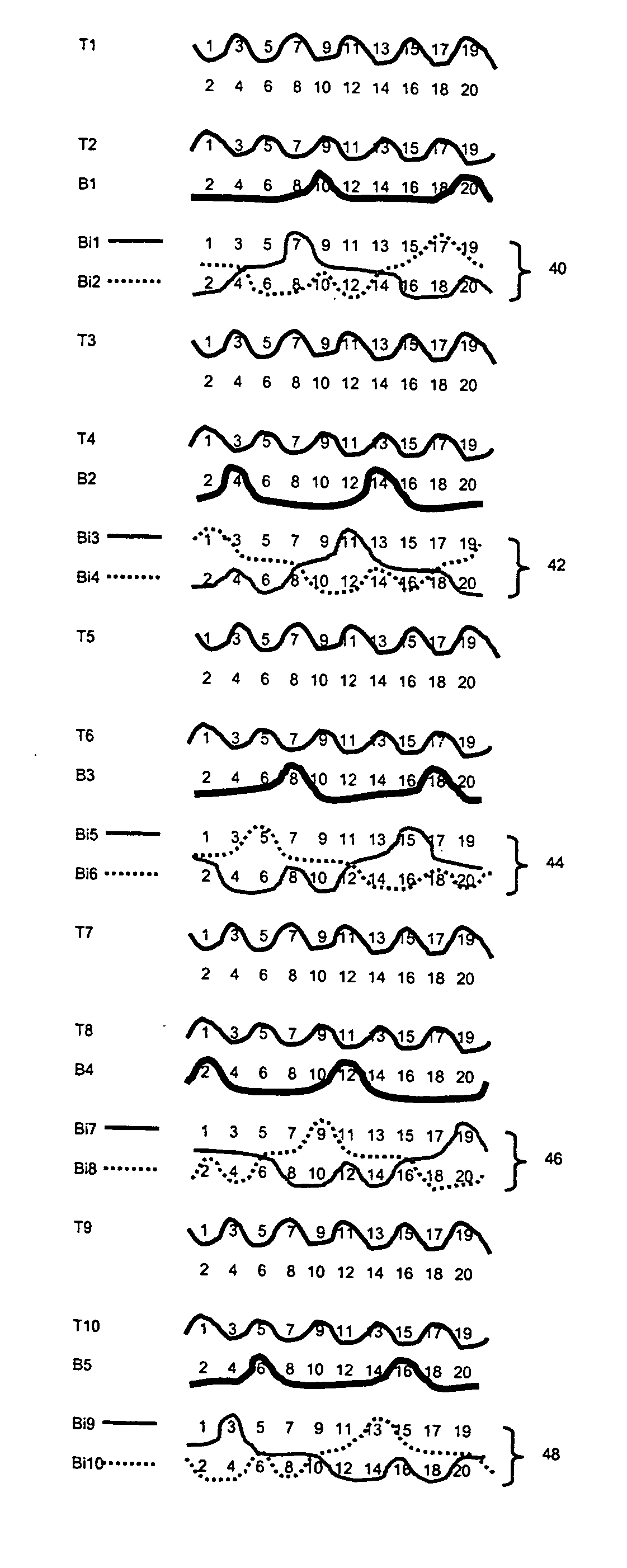
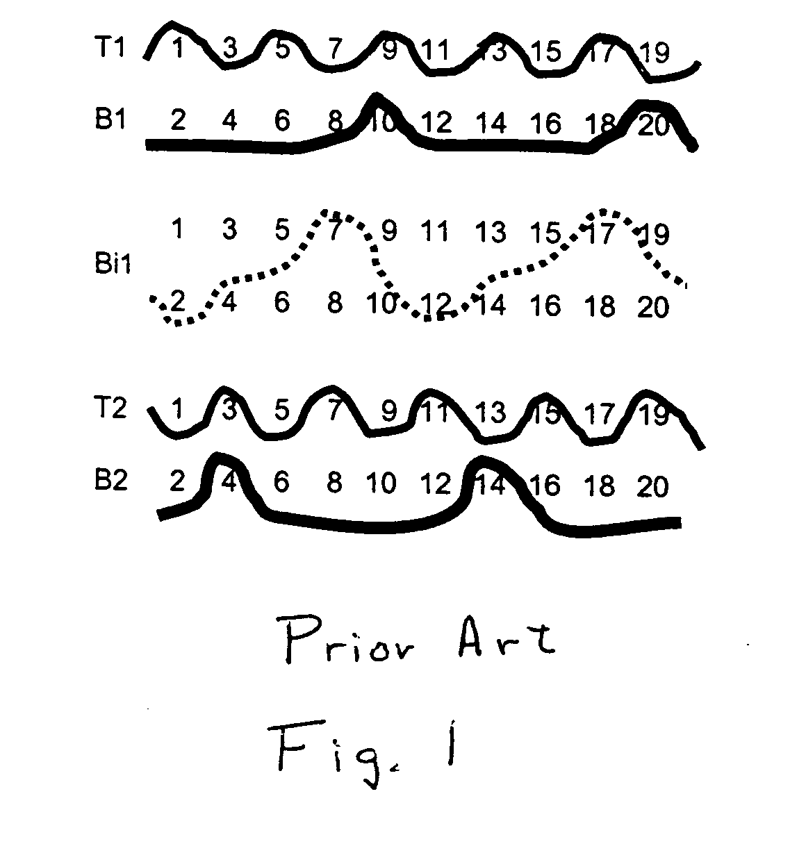
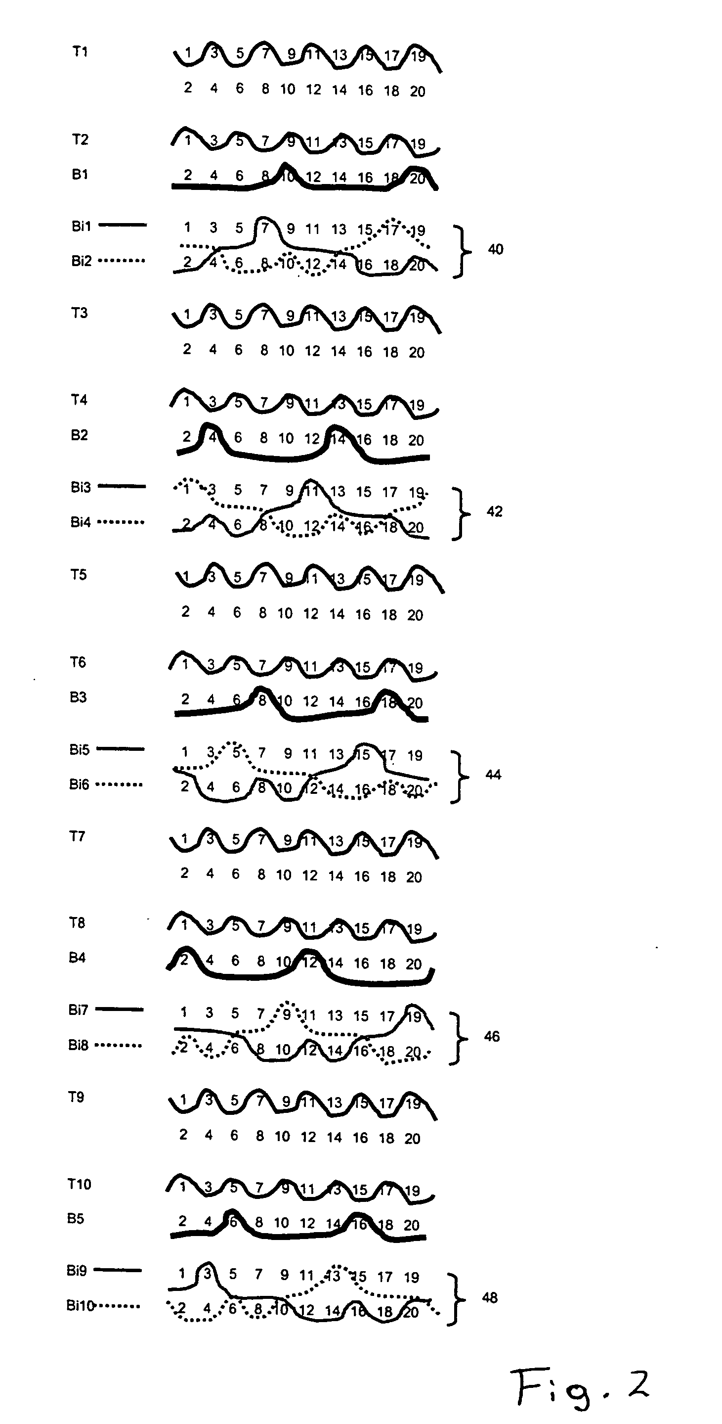
[0035] Referring now to the drawings, and, more particularly to FIG. 1, there is shown a series of weft yarns arranged in accordance with a 20 shaft weave.

[0036]FIG. 1 shows how each of the weft yarns interacts with the twenty warp yarns in the fabric's warp repeat unit. There is a 1:1 paper side to wear side warp ratio, comprising paper side warps 1, 3, 5, 7, 9, 11, 13, 15, 17 and 19, and machine side warps 2, 4, 6, 8, 10, 12, 14, 16, 18, 20.

[0037] The weft yarns fall into three categories. The first set of weft yarns, as exemplified by wefts B1 and B2, bind only with the machine side warps, binding with every fifth wear side warp yarn such that the machine or wear side fabric has a so-called five shaft back. The second set of weft yarns, as exemplified by wefts T1 and T2, bind only with the paper side warps, to each form complete weave repeats in an over-under fashion. Thus, the paper side fabric has a so-called plain weave face.

[0038] The remaining weft Bi1, in FIG. 1, provide...


PUM


Abstract

A forming fabric having a set of paper side warp yarns, which interlace with both a set of paper side weft yarns and a set of binder wefts and a set of machine side warp yarns which interlace with a set of machine side weft yarns and the set of binder weft yarns, whereby the binder weft yarns are disposed in groups of at least two, and whereby both binder weft yarns of at least one binder group, in total, form fewer knuckles over the paper side warp yarns than the paper side weft yarns.

Description

BACKGROUND OF THE INVENTION [0001] 1. Field of the Invention [0002] The present invention relates to fabrics employed in web forming equipment, such as papermaking and non-woven web forming equipment, and, more particularly, to forming fabrics in web forming equipment; most preferably in papermaking machines. [0003] 2. Description of the Related Art [0004] Paper is conventionally manufactured by conveying a paper furnish, usually consisting of an initial slurry of cellulose fibers, on a forming fabric or between two forming fabrics in a forming section, the nascent sheet then is passed through a pressing section and ultimately through a drying section of a papermaking machine. In the case of standard tissue paper machines, the paper web is transferred from the press fabric to a Yankee dryer cylinder and then creped. [0005] Papermachine fabric is essentially employed to carry the paper web through these various stages of the papermaking machine. In the forming section the fibrous fur...

Claims


Application Information

Patent Timeline
Patent Type & Authority Applications(United States)
IPC IPC(8): D21F1/00
CPCD21F1/0045Y10T442/3179
Inventor QUIGLEY, SCOTTKRAMER, JIMBREWSTER, JAMESHAY, STEWART LISTER
Owner VOITH PATENT GMBH
Why Eureka
Try Eureka