Wideband compact planar inverted-F antenna

a compact, inverted-f antenna technology, applied in the structure of radiating elements, substantially flat resonant elements, resonance antennas, etc., can solve the problems of increasing the complexity of the handset, increasing the bandwidth parameter of most applications, and introducing difficulties into the feed system, so as to improve bandwidth and improve performance characteristics.

Inactive Publication Date: 2011-09-06
VIRGINIA TECH INTPROP INC
View PDF13 Cites 0 Cited by
  • Summary
  • Abstract
  • Description
  • Claims
  • Application Information

AI Technical Summary

Benefits of technology

[0009]It is therefore a general object of the present invention to provide a low profile, PIFA-style anten

Problems solved by technology

Dual band antennas have been used to meet this need, however, many dual band antennas use a dual feed which introduces difficulties into the feed system.
It is possible, but expensive to place multiple antennas on handsets and it also increases the complexity of the handset.
This parameter of bandwidth is limited in most applications by the need to match the i

Method used


Image

  • Wideband compact planar inverted-F antenna
  • Wideband compact planar inverted-F antenna
  • Wideband compact planar inverted-F antenna

Examples


Embodiment Construction

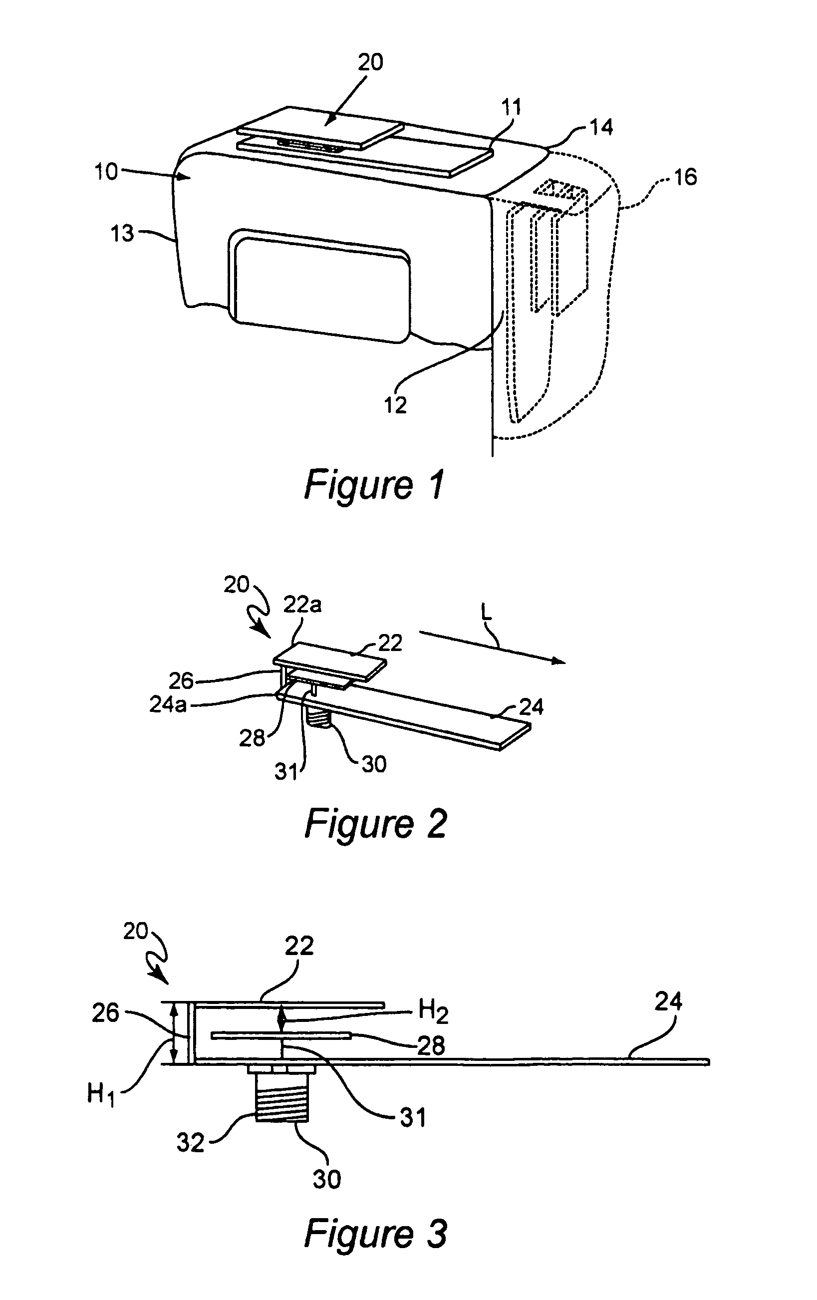
[0026]FIG. 1 illustrates a wireless handset, such as a cellular telephone or portable radio 10 to which an antenna 20 constructed in accordance with the principles of the present invention is attached. The antenna 20 is shown disposed along the top surface 11 of the handset 10, but may be attached at other suitable locations on the handset 10, such as either of the side surfaces 12, 13 or rear surface 14. A side mounting of the antenna 20 is shown in FIG. 1 in dashed line. Typically, the antenna 20 will be enclosed within a protective housing 16, or within the handset housing, but electrically isolated from the handset circuitry except for the connector.

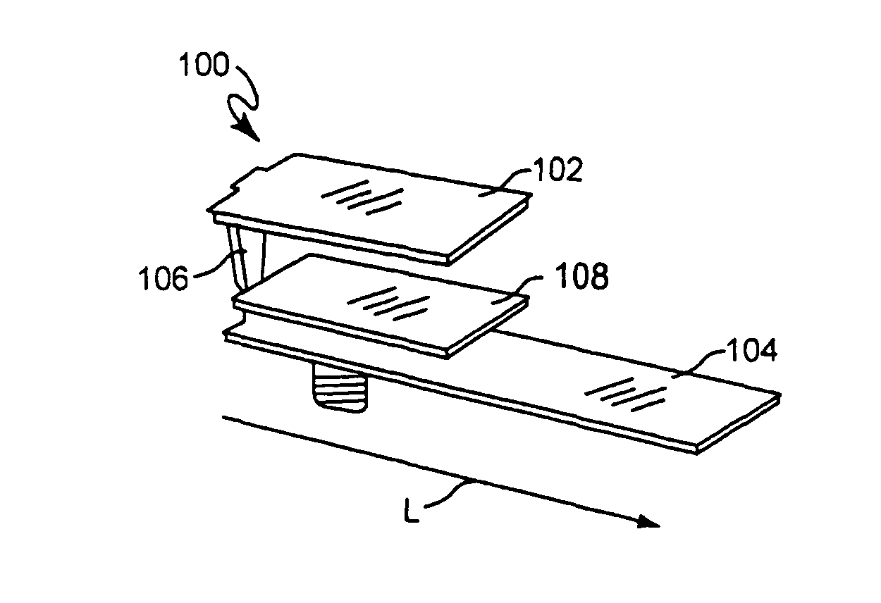
[0027]FIG. 2 illustrates, in perspective one embodiment of a low profile antenna 20 constructed in accordance of the principles of the present invention. As shown best in FIGS. 2 and 3, the antenna 20 is of a “PIFA” style, that is a planar, inverted-F antenna. In this regard, the antenna 20 shown has a first conductive plate 22 and a...


PUM


Abstract

An improved low profile antenna of the PIPAPIFA style is formed from a single piece of useful conductive material and includes a first plate spaced apart from an elongated ground plate. The first and ground plates are interconnected by a shorting plate having a width less than that of either the first or ground plate. A feed plate is interposed between the two plates and is either completely covered by the first plate or slightly exposed. Such antennas have extremely large bandwidth of up to about 50%.

Description

[0001]This application is a 371 of PCT / US01 / 13603 filed Apr. 27, 2001 which claims benefit of Ser. No. 60 / 200,009 filed Apr. 27, 2000.BACKGROUND OF THE INVENTION[0002]The present invention relates generally to planar inverted-F antennas, and more particularly to such an antenna with improved performance characteristics that is particularly suitable for use in wireless telephones.[0003]The wireless communication industry has expanded rapidly and many different frequency bands have been implemented. A need exists for wireless devices that operate in multi-frequency bands. Dual band antennas have been used to meet this need, however, many dual band antennas use a dual feed which introduces difficulties into the feed system. Dual band antennas permit wireless handsets to operate in different networks that have different frequencies. There are more than three frequency bands used in the world for wireless communications. It is possible, but expensive to place multiple antennas on handset...

Claims


Application Information

Patent Timeline
IPC IPC(8): H01Q1/24H01Q5/00H01Q9/04
CPCH01Q9/0414H01Q9/0421H01Q5/378H01Q5/357H01Q9/045
Inventor STUTZMAN, WARREN L.HUYNH, MINH-CHAU
Owner VIRGINIA TECH INTPROP INC
Why Eureka
Try Eureka