Optical inspection system, apparatus and method for reconstructing three-dimensional images for printed circuit board and electronics manufacturing inspection

an optical inspection system and three-dimensional image technology, applied in the field of optical inspection systems, can solve the problems of additional time, inability to apply photometric stereo methods to optical inspection of mostly specular objects, and inability to apply techniques in the optical inspection industry of printed circuit boards, so as to improve the user's accuracy in detecting defective objects

Inactive Publication Date: 2006-03-28
AGILENT TECH INC
View PDF23 Cites 66 Cited by
  • Summary
  • Abstract
  • Description
  • Claims
  • Application Information

AI Technical Summary

Benefits of technology

[0011]The ability to display an image of the inspected object in greater than two dimensions can improve the user accuracy in detecting defective objects by providing more information to the user about the shape of the object. Furthermore, the invention provides embodiments with other features and advantages in addition to or in lieu of those discussed above. Many of these features and advantages are apparent from the description below with reference to the following drawings.

Problems solved by technology

Although a number of techniques for reconstructing a three-dimensional image from multiple two-dimensional images are known in the computer vision industry, these techniques have not been applied to the printed circuit board optical inspection industry due to the difficulty in processing the specular reflections off shiny specular objects, such as solder joints and other components present on PCBs.
However, photometric stereo methods have not been applied to optical inspection of mostly specular objects (e.g., solder joints on printed circuit boards) due to the additional processing required to analyze both the specular and diffuse reflections, and therefore the additional time required for each inspection.
The manual inspection process is labor-intensive and prone to errors.
In many cases, two-dimensional images do not provide enough information to accurately assess whether or not an object is defective.

Method used


Image

  • Optical inspection system, apparatus and method for reconstructing three-dimensional images for printed circuit board and electronics manufacturing inspection
  • Optical inspection system, apparatus and method for reconstructing three-dimensional images for printed circuit board and electronics manufacturing inspection
  • Optical inspection system, apparatus and method for reconstructing three-dimensional images for printed circuit board and electronics manufacturing inspection

Examples


Embodiment Construction

[0039]The numerous innovative teachings of the present application will be described with particular reference to the exemplary embodiments. However, it should be understood that these embodiments provide only a few examples of the many advantageous uses of the innovative teachings herein. In general, statements made in the specification do not necessarily delimit any of the various claimed inventions. Moreover, some statements may apply to some inventive features, but not to others.

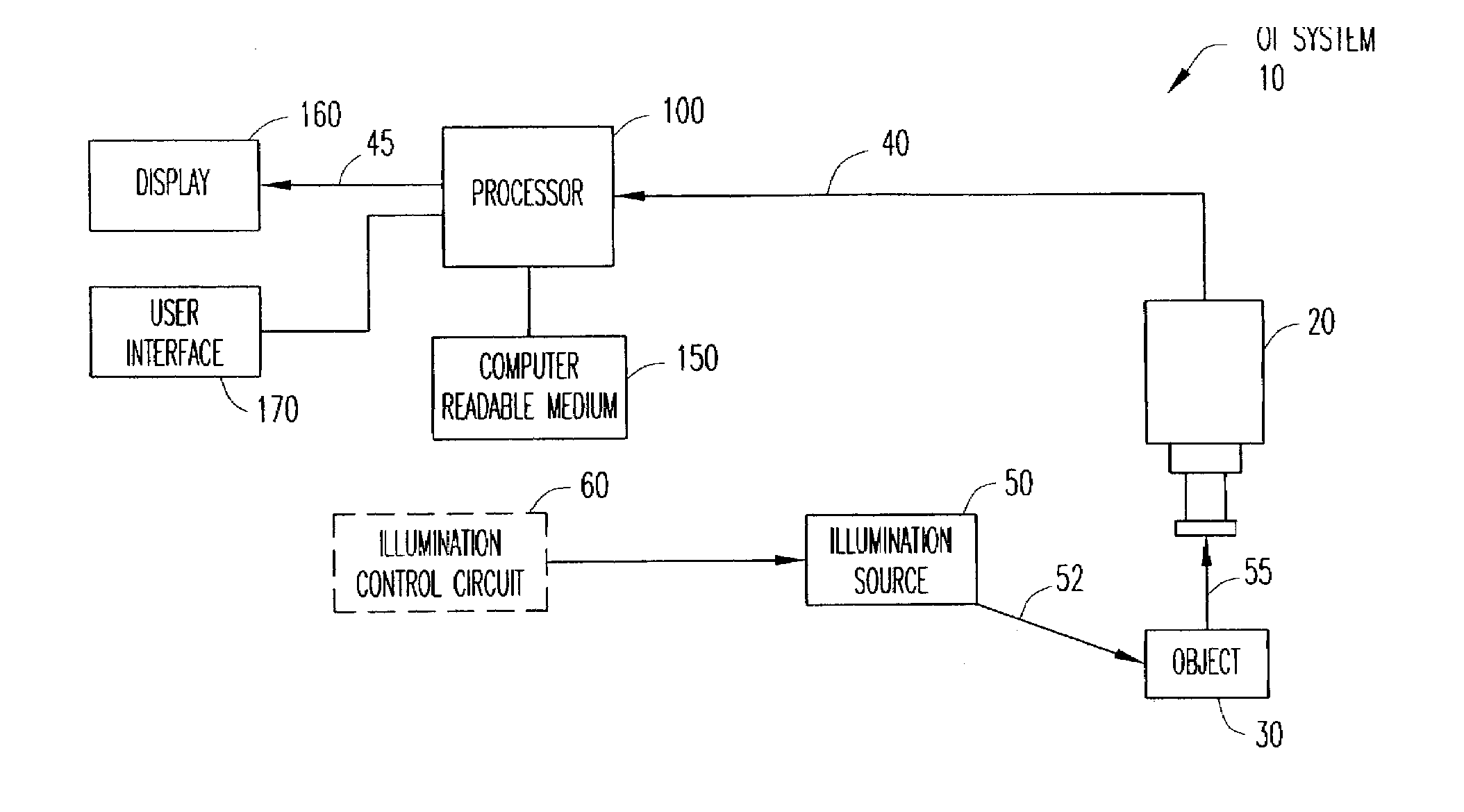
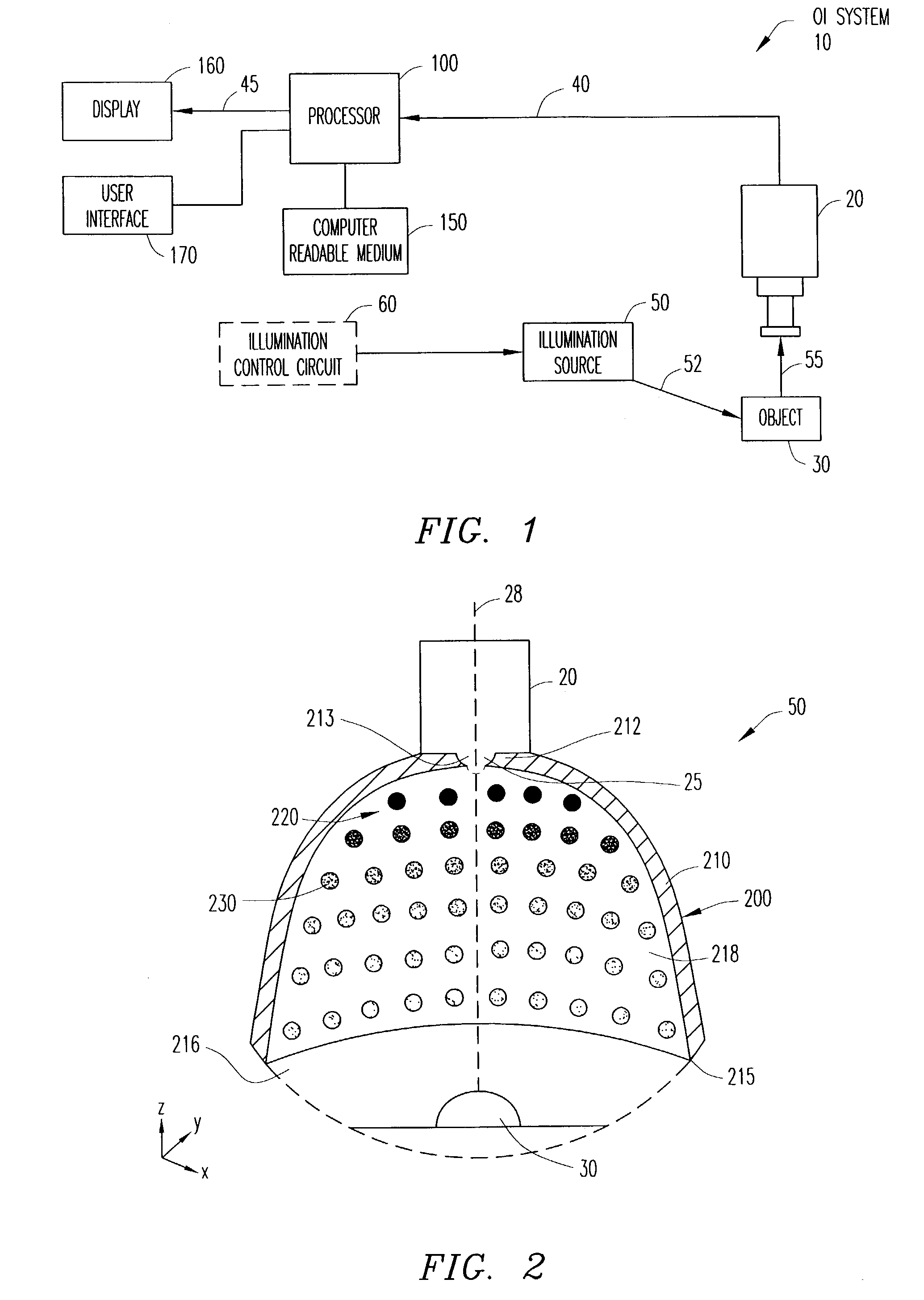
[0040]Referring now to FIG. 1, there is illustrated a simplified schematic of an optical inspection (OI) system 10 capable of rendering a three-dimensional image 45 of the surface of an object 30, which can have both specular and diffuse surface reflection elements, in accordance with embodiments of the present invention. The OI system 10 includes an illumination source 50 for illuminating the surface of an object 30 and a sensing apparatus (e.g., camera) 20 for capturing an image of the surface of the o...


PUM

PropertyMeasurementUnit
shapeaaaaaaaaaa
optical inspectionaaaaaaaaaa
elevationsaaaaaaaaaa

Abstract

A three-dimensional optical inspection system reconstructs a three-dimensional image of the shape of the surface of an at least partially specular object resident on a printed circuit board by capturing two or more two-dimensional images of the object under different illumination configurations. The diffuse reflection, as well as the specular reflection can be used to reconstruct the three-dimensional image using any reconstruction method, such as photometric stereo. The different illumination configurations can be achieved using an illumination source including light-emitting elements arranged in concentric circular arrays, in which each of the circular arrays is divided into sections. Each section is independently controlled to selectively activate the sections to illuminate the object in a pre-established illumination pattern.

Description

CROSS-REFERENCE TO RELATED APPLICATIONS[0001]This U.S. Nonprovisional Application for Patent is related by subject matter to copending and commonly assigned U.S. Nonprovisional Applications for patent Ser. Nos. 10 / 392,758, 10 / 392,948 and 10 / 393,413. U.S. Nonprovisional Applications for patent Ser. Nos. 10 / 392,758, 10 / 392,948 and 10 / 393,413 are hereby incorporated by reference in their entirety.BACKGROUND OF THE INVENTION[0002]1. Technical Field of the Invention[0003]The present invention relates generally to the field of optical inspection systems. More particularly, the present invention relates to systems and methods for reconstructing three-dimensional images of specular objects for printed circuit board and electronics manufacturing inspection.[0004]2. Description of Related Art[0005]In conventional optical inspection systems, the data collected produce a two-dimensional image of a three-dimensional object. For example, in optical inspection of printed circuit boards (PCBs), the...

Claims


Application Information

Patent Timeline
Patent Type & Authority Patents(United States)
IPC IPC(8): G01N21/00G01N21/88G06K9/00G06T7/00G06T7/60
CPCG06T7/0002G06T7/0073G06T7/602G06T2207/30152G06T2207/30141G06T7/586G06T7/62G01N21/00G06T7/60
Inventor VOOK, DIETRICH W.BAHARAV, IZHAKZHANG, XUEMEIKAKARALA, RAMAKRISHNABAER, RICHARD L.
Owner AGILENT TECH INC
Why Eureka
Try Eureka