Modulator circuitry

a module and circuit technology, applied in the field of modules, can solve the problems of affecting the switching of sources, affecting the quality of the module, and the amount of raw data to describe the pattern is enormous,

Inactive Publication Date: 2006-03-28
ASML NETHERLANDS BV
View PDF5 Cites 187 Cited by
  • Summary
  • Abstract
  • Description
  • Claims
  • Application Information

AI Technical Summary

Benefits of technology

[0017]A further or other objective of the current invention is to provide a modulator which enables stable operation of an optical or charged particle beam lithography system.
[0047]In an embodiment of the electron beam maskless lithography system, the projecting means comprise a first demagnifier with a reduction optical system for demagnifying the plurality of modulated light beams and a projection optical system for projecting the demagnified plurality of modulated light beams on said electrostatic deflector aperture array. In an embodiment thereof, said reduction optical system comprises a micro lens array, each micro lens of said micro lens array being aligned with one of said plurality of modulated light beams and adapted for reducing the size of said one of said modulated light beams. In a further embodiment thereof, said projection optical system further comprises a mirror, for reflecting the plurality of modulated, demagnified light beams coming from the reduction optical system in the direction of said lens of the projection optical system.

Problems solved by technology

Since a mask is a highly efficient way to store a pattern, the amount of raw data to describe a pattern is enormous.
Additionally the high data rate must be obtained within limited space.
The switching of sources may get problematic when the switching speed increases.
The settling time of a source can for instance be too long.
However, the bandwidth of a metal wire is limited.
This takes an enormous amount of space and is difficult to handle.

Method used


Image

  • Modulator circuitry
  • Modulator circuitry
  • Modulator circuitry

Examples


example 1

Maskless Electron Beam Lithography System

[0138]FIGS. 10–12 show several parts of this system. In the maskless electron beam lithography system used in this example, the system comprises an aperture plate comprising electrostatic deflectors 21 to deflect incoming electron beamlets 22 passing through the apertures 23. This plate will be referred to as the beamlet blanker array 24. When the electron beamlets 22 have passed the beamlet blanker array 24 they will reach a second aperture array on which their trajectory will terminate when they are deflected. The second plate is referred to as the beamlet stop array 25.

[0139]The modulation concept of this lithography system is shown in FIG. 10. Incoming electron beamlets 22 are projected on the beamlet blanker array 24. The positions of the electron beamlets 22 correspond to the positions of the apertures 23 in the plate 24. The beamlet blanker plate 24 comprises a deflector element as modulation means. In this example said deflector eleme...

example 2

Maskless EUV-Light Optical Lithography System

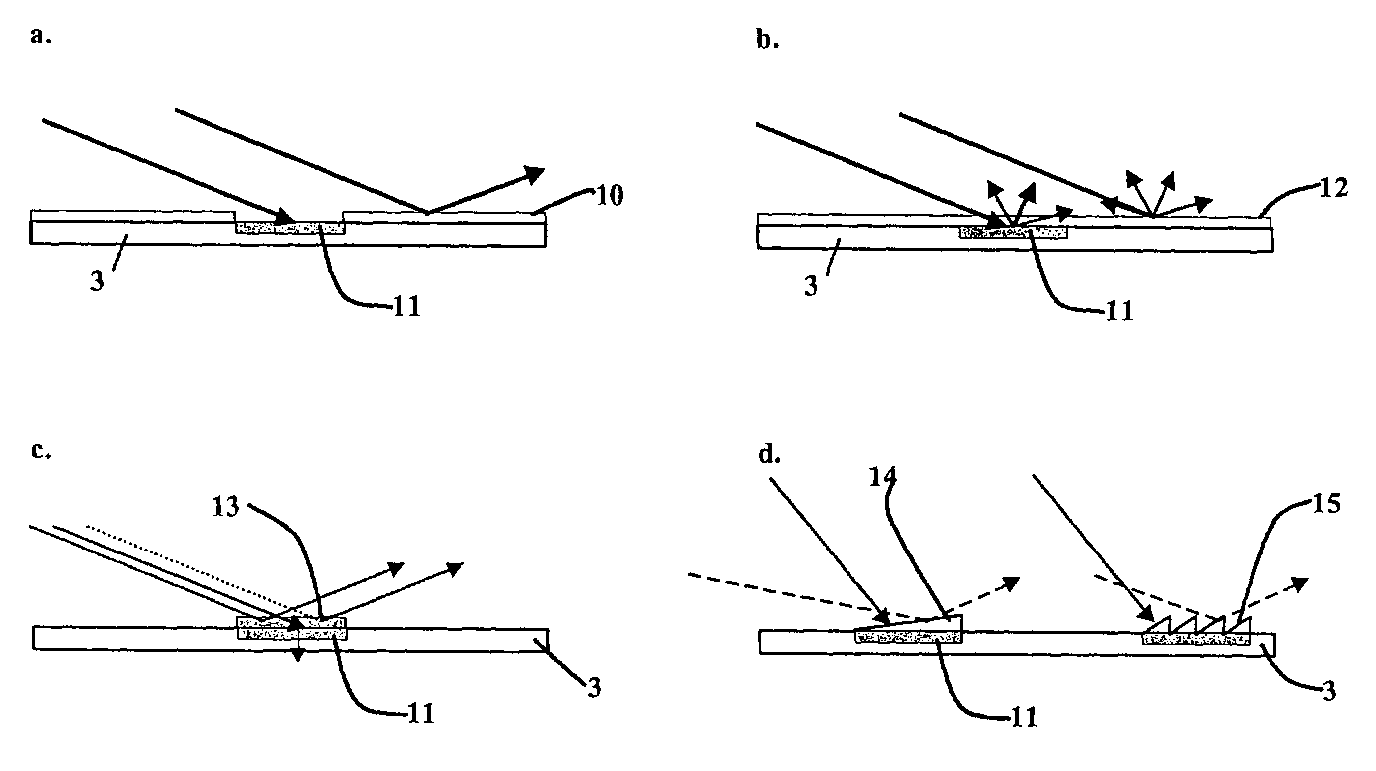
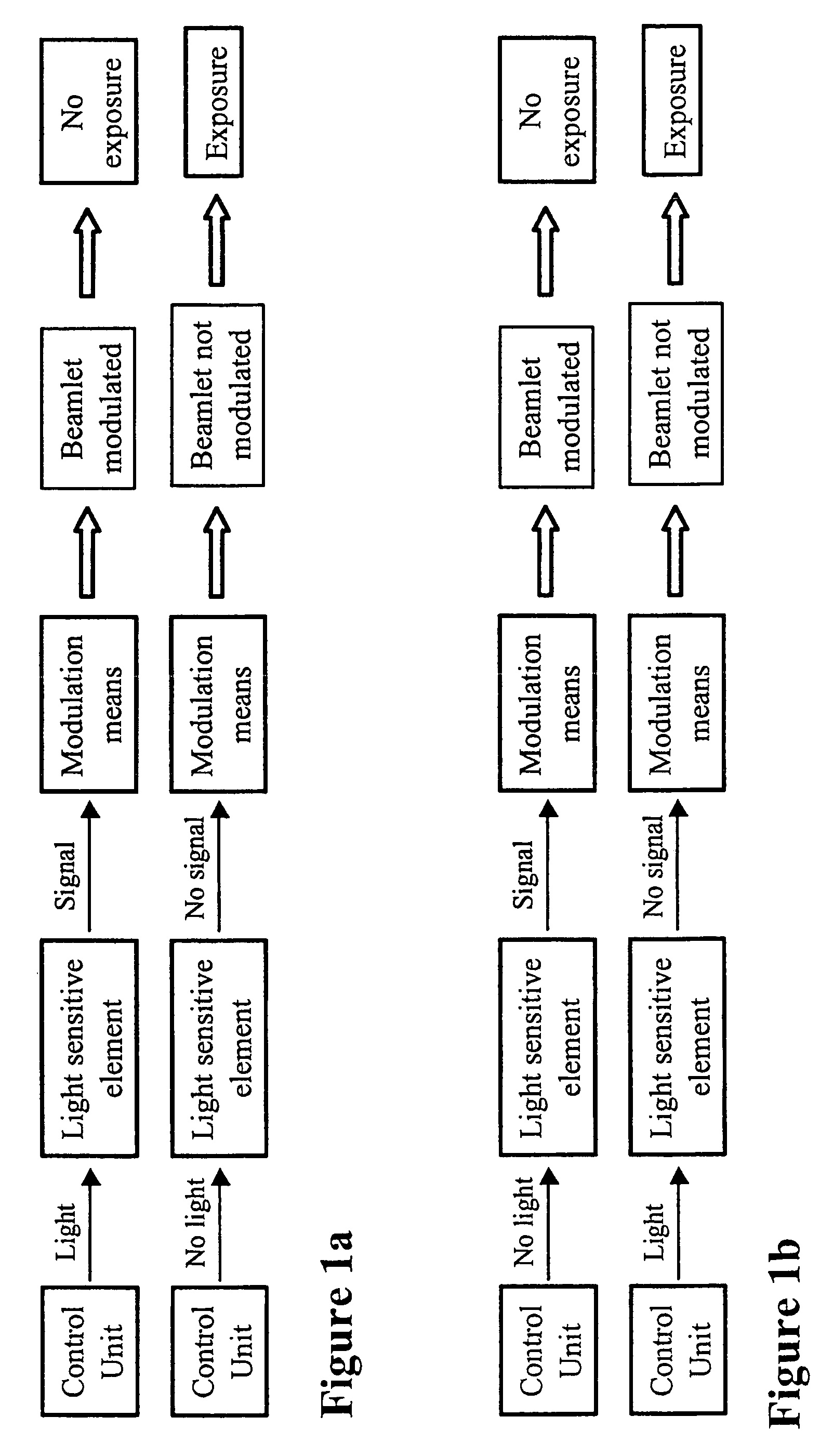
[0141]The maskless EUV system in this example, schematically shown in FIG. 13, comprises a spatial light modulator (SLM). Maskless lithography systems using an SLM can be found in for instance WO0118606. The SLM comprises an array of mirrors, which reflect the incoming light beams in such a way that the beam eventually is blanked or transmitted. An example of such an SLM is a deformable mirror device (DMD). A DMD is controlled in the same way as the electrostatic deflector array shown in the first example. The modulation signals couple into the system from the back or from the side. The most probable configuration would be a backside control of the modulation. By providing the backside of each mirror with a light sensitive element, the control can be done with the use of the same optical carriers as mentioned before. Probably the use of free space optical interconnects is the most convenient option.

[0142]A schematic drawing of the operati...


PUM

PropertyMeasurementUnit
wavelength rangeaaaaaaaaaa
frequencyaaaaaaaaaa
wavelengthsaaaaaaaaaa

Abstract

The invention relates to a modulator for modulating the magnitude of a beamlet in a multi-beamlet lithography system, said modulator comprising at least one means for influencing the direction of a beamlet, a light sensitive element for receiving light from a modulated light beam and converting said light into a signal, and discretizing means, coupling to said light sensitive element and to at least one of means for influencing, for converting said signal received from said light sensitive element into a discrete signal having discrete values selected from a set of predefined discrete values and providing said discrete signal to said means for influencing.

Description

[0001]This application claims the benefit of Provisional Application No. 60 / 491,475, filed Jul. 30, 2003.BACKGROUND[0002]The invention pertains to a modulator for modulating the magnitude of a beamlet in a multi-beamlet lithography system, in particular for a maskless lithography system.[0003]Maskless lithography systems, including ion, laser, EUV and electron beam systems, all require means to process and deliver pattern data to some kind of writing means. Since a mask is a highly efficient way to store a pattern, the amount of raw data to describe a pattern is enormous. Moreover, for a commercially acceptable throughput, the data must be transported towards the writing means at a very high data rate. Additionally the high data rate must be obtained within limited space. It was up to now not recognized that improvement of the data path in maskless lithography systems has a profound effect on the throughput of these systems.[0004]All maskless lithography systems can be divided in tw...

Claims


Application Information

Patent Timeline
Patent Type & Authority Patents(United States)
IPC IPC(8): G02B27/10G02B26/00G02F1/01G03B27/42G03F7/20G21K5/10H01J37/08H01J37/317
CPCB82Y10/00B82Y40/00G03F7/70383H01J37/3177G03F7/70291H01J2237/0435G03F7/20
Inventor VAN 'T SPIJKER, JOHANNES CHRISTIAANWIELAND, MARCO JAN-JACOHABEKOTTE, ERNSTVAN DER WILT, FLORIS PEPIJN
Owner ASML NETHERLANDS BV
Why Eureka
Try Eureka