
Optical information recording medium, and method and apparatus for recording/reproducing information thereon

a technology of optical information and recording medium, which is applied in the field of optical information recording medium, can solve the problems of reducing the intensity of the signal obtained from the wobble, deteriorating signal quality, and inability to obtain good circuit control signals, so as to achieve easy and reliable recording/reproduction of information, easy detection of address information, and large capacity

Inactive Publication Date: 2006-03-28
PANASONIC CORP
View PDF35 Cites 0 Cited by
  • Summary
  • Abstract
  • Description
  • Claims
  • Application Information

AI Technical Summary

Benefits of technology

[0015]Therefore, with the foregoing in mind, it is an object of the present invention to provide an optical information recording medium with a large capacity that can achieve easy and reliable recording / reproduction of information. More specifically, first, it is an object of the present invention to provide an optical information recording medium that can achieve easy detection of address information while using the land & groove recording method and the CLV method. Secondly, it is another object of the present invention to provide an optical information recording medium that allows stable recording / reproduction of information even when the recording medium includes two or more recording layers, and information is recorded / reproduced on / from a recording layer with laser light that has passed through another recording layer. Thirdly, it is another object of the present invention to provide an optical information recording medium that can achieve efficient and reliable recording / reproduction of information even when information is recorded / reproduced successively and continuously on / from a plurality of recording layers.
[0017]The first recording medium of the present invention makes it possible to detect the address information reliably when the CLV method is used together with the land & groove method, so that the present invention allows stable recording / reproduction of information.
[0021]The second recording medium allows stable recording / reproduction of information, even when information is recorded / reproduced with laser light that has passed through another recording layer. In this medium, even if the transmittance of the laser light is different between the information recording regions and the address regions, the address regions do not form a block but are dispersed. Therefore, transmitted laser light hardly affects the recording layer. The difference in the transmittance of the laser light is made typically by formation of recording marks on the information recording regions.

Problems solved by technology

Thus, good circuit control signals cannot be obtained.
Therefore, the signal amplitude is varied during reproduction of information, so that signal quality is deteriorated.
On the other hand, when the amplitude of the wobble is reduced as well, the intensity of the signal obtained from the wobble is reduced, which makes it difficult to detect address information.

Method used


Image

  • Optical information recording medium, and method and apparatus for recording/reproducing information thereon
  • Optical information recording medium, and method and apparatus for recording/reproducing information thereon
  • Optical information recording medium, and method and apparatus for recording/reproducing information thereon

Examples


first embodiment

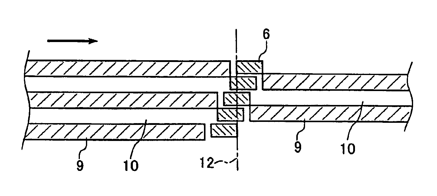
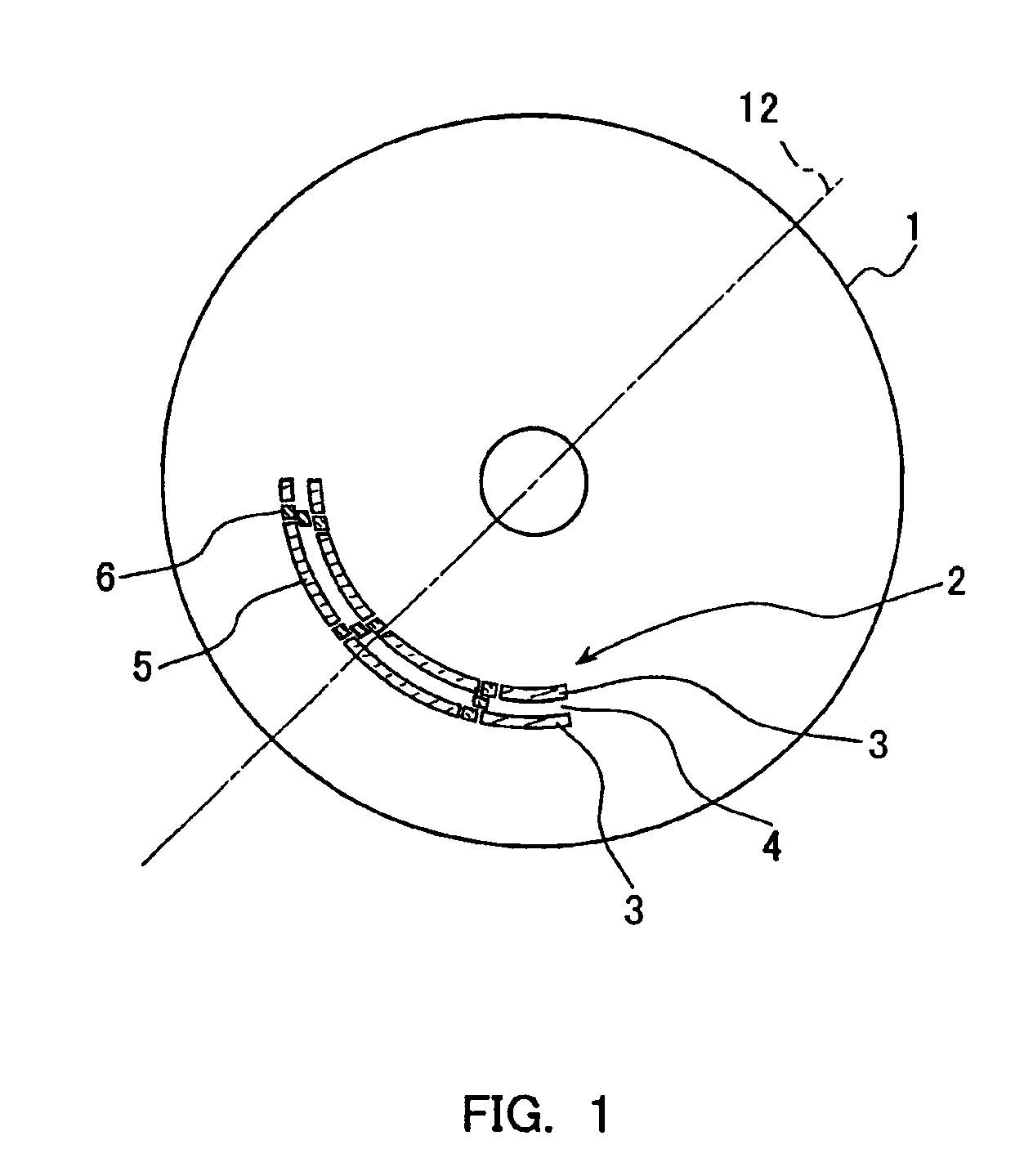
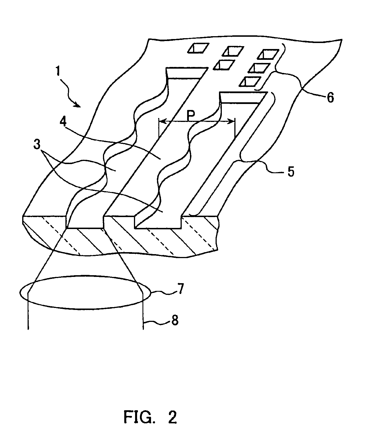
[0048]An optical information recording medium of the present invention includes a recording layer (not shown) on a transparent substrate 1 having a thickness, for example, of 0.6 mm. The substrate 1 is formed of polycarbonate or the like and is provided with a circular center hole in its center with which the substrate is mounted on a recording / reproducing apparatus, as shown in FIG. 1. The recording layer is formed, for example, of a GeSbTe alloy, which is a phase change recording material. In many cases, the recording layer formed of such a phase change recording material is initialized (crystallized) for use. The recording layer is made amorphous locally by irradiation of laser light to form recording marks. The substrate 1 previously is provided with a spiral information track 2 that is tracked by laser light during recording / reproduction and on which information is recorded. The information track 2 includes grooves 3 and lands 4 that are formed alternately in the radial directi...

embodiment 3

[0069]In an optical information recording medium of this embodiment, as shown in FIG. 7, the spiral directions of the information tracks of the first recording layer 14 and the second recording layer 16 are opposite to each other when viewed from the laser light 19 incident side. Therefore, seamless recording or seamless reproduction that uses the capacity of the recording medium to the maximum can be achieved by using these two recording layers alternately.

[0070]For example, in FIG. 7, information can be recorded (or reproduced) in the following manner. First, the laser light 19 is focused on the second recording layer 16, and information is recorded from an inner circumferential end A of a second groove 22 toward the outer circumference. When the laser light 19 reaches an outer circumferential end B, the laser light is focused on an outer circumferential end C in a first groove 20 of the first recording layer 14. Furthermore, information is recorded toward the inner circumference ...

embodiment 4

[0076]This embodiment shows a variation of the prepit addresses in the address regions shown in the above embodiments. In the optical information recording medium of this embodiment shown in FIG. 8, as in the recording medium of Embodiment 1 shown in FIG. 1, a recording layer (not shown) is provided on the substrate 1 on which grooves 3 and lands 4 are formed. The recording layer formed on the surfaces of the groove and the land is provided with information tracks 2. The information track 2 has a sector format structure in which information recording regions 75 and address regions 76 are arranged alternately along the radial direction of the disk.

[0077]Also in this optical information recording medium, as shown in FIG. 9, only one edge of the groove 3 is wobbled at a constant spatial frequency in the recording regions 75. Since the other edge is not wobbled, the wobbled edges are arranged at every two edges in the radial direction of the disk. In the address regions 76, prepit addre...


PUM

PropertyMeasurementUnit
thicknessaaaaaaaaaa
wavelengthaaaaaaaaaa
widthaaaaaaaaaa

Abstract

The present invention relates to an optical information recording medium including a disk-shaped transparent substrate and a recording layer for recording, reproducing or erasing information by irradiation of laser light, the recording layer being formed over the substrate. The recording layer of the present invention includes information tracks including groove tracks and land tracks that are formed alternately in a radial direction of the disk. The information tracks comprise information recording regions and address regions interposed between the information recording regions, the information recording regions and the address regions being arranged along the tracking direction of the laser light. In the information recording regions, every second step in the radial direction of steps for dividing the groove tracks from the land tracks adjacent to the groove tracks is wobbled in the tracking direction, and in a range whose ends are defined by the address regions the every second step is wobbled at a constant frequency. Prepit addresses for providing information on a position on the recording medium are formed on the address regions. Moreover, the present invention provides an optical information recording medium including n recording layers (where n is an integer of at least 2), and in at least the first recording layer to the (n-1)th recording layer from the transparent substrate side, no pair of adjacent address regions in the radial direction of the disk are arranged so as to be aligned on a straight line passing through the center of the disk.

Description

[0001]“This application is a divisional of application Ser. No. 09 / 812,533, filed Mar. 20, 2001 now U.S. Pat. No. 6,754,143, which application(s) are incorporated herein by reference.”BACKGROUND OF THE INVENTION[0002]1. Field of the Invention[0003]The present invention relates to an optical information recording medium for recording / reproducing information by irradiation of laser light, and further relates to a method and an apparatus for recording / reproducing information on this medium.[0004]2. Description of the Prior Art[0005]Optical information media have been noted widely as a large capacity and high density memory, and erasable media that can be rewritten have been under development at present. In one of the erasable optical information recording media, a recording layer made of a phase change material that changes between an amorphous state and a crystalline state is formed on a substrate, and information is recorded and erased by irradiating the recording layer with laser li...

Claims


Application Information

Patent Timeline
Patent Type & Authority Patents(United States)
IPC IPC(8): G11B7/00G11B7/007G11B27/19G11B27/24G11B27/30
CPCG11B7/007G11B7/00718G11B7/00745G11B27/24G11B2220/2575G11B2220/216G11B2220/218G11B2220/2529G11B2220/2545G11B27/3027
Inventor AKIYAMA, TETSUYANISHIUCHI, KENICHINARUMI, KENJI
Owner PANASONIC CORP
Learn More