Grounding plate assembly for a drum in an image forming apparatus

a technology of image forming apparatus and grounding plate, which is applied in the direction of electrographic process apparatus, instruments, optics, etc., can solve the problems of unsatisfactory above arrangement, poor image quality, and no drum function

Inactive Publication Date: 2006-03-28
MITSUBISHI CHEM AMERICA
View PDF11 Cites 86 Cited by
  • Summary
  • Abstract
  • Description
  • Claims
  • Application Information

AI Technical Summary

Problems solved by technology

The above arrangement can be unsatisfactory due to the requirement for the radially projecting contact element to be aligned with the scribed patch formed on the inner surface of the photosensitive drum.
If a radially extending projection does not contact with the scribed portion or contact area on the interior of the drum, although a certain amount of grounding might take place, it is certainly less than optimal.
As a result, the drum will not function or will provide inferior image quality.
Since inferior images can result from a wide array of problems, this problem is also difficult to detect, and results in an overall perception of inferior image forming products.
Thus, prior arrangements have been problematic in that they rely upon the care of the laborer in inserting the flange into the end of the drum to ensure that the contact projection of the grounding plate is aligned with the contact area of the interior surface of the drum.
Moreover, even if care has been taken in aligning the contact projection of the grounding plate with the contact surface on the interior of the drum, any movement of the flange after insertion (e.g., if the flange should move before the adhesive utilized in securing the flange to the drum has cured), inferior contact can nevertheless result.
The requirement to align the contact projection of the grounding plate with the contact area on the inner surface of the drum also presents a complication or obstacle to automation.

Method used


Image

  • Grounding plate assembly for a drum in an image forming apparatus
  • Grounding plate assembly for a drum in an image forming apparatus
  • Grounding plate assembly for a drum in an image forming apparatus

Examples


Embodiment Construction

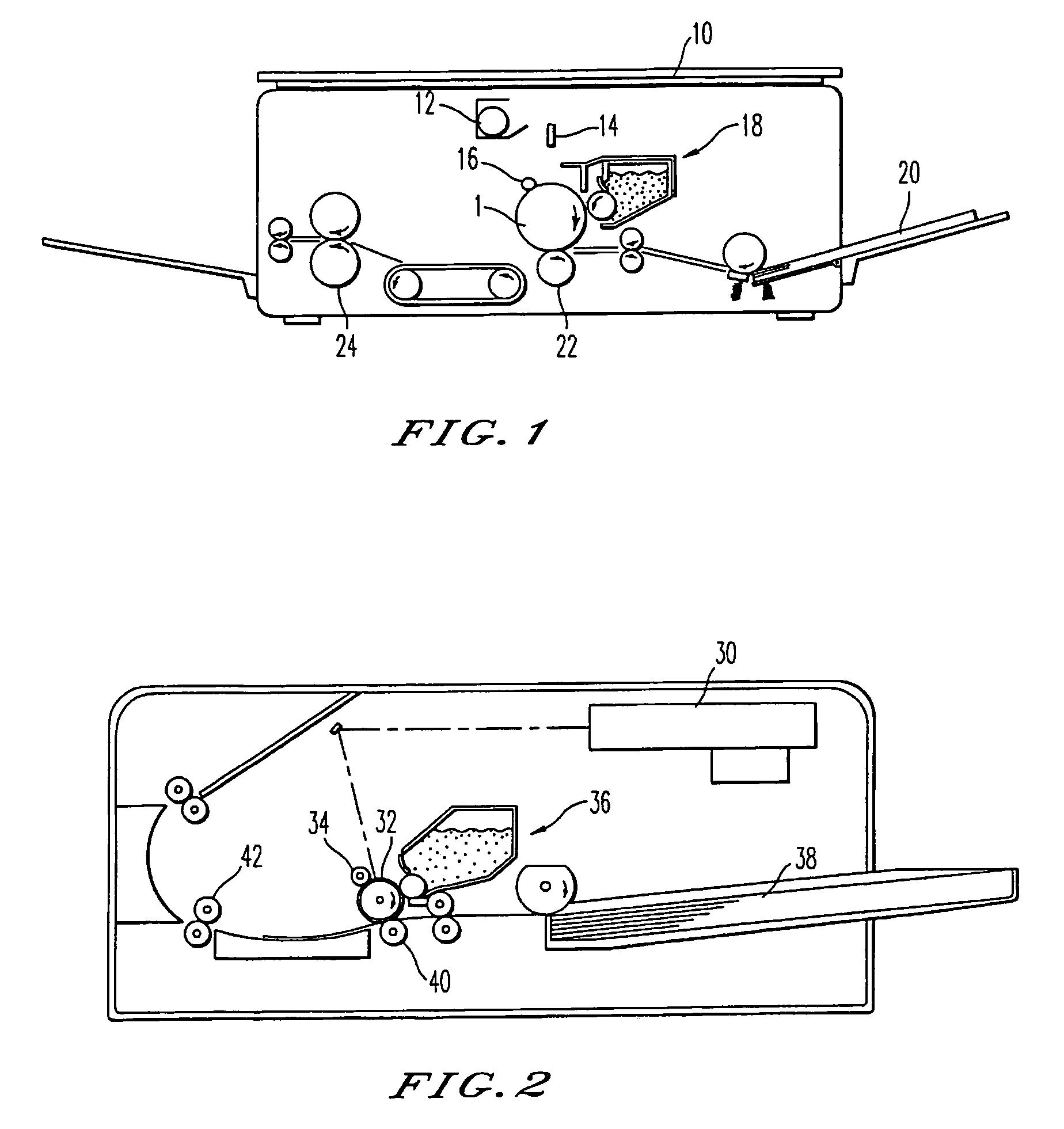
[0022]FIG. 1 schematically represents an image forming apparatus in the form of a photocopier to which the present invention is applicable. In such an arrangement, an original document is placed upon the photocopier glass 10, and is illuminated by a lamp 12. The resulting light is then projected onto a photosensitive drum 1 by way of an optical system 14, and the drum has been previously charged utilizing, for example, a charge roller 16. As a result, an electrostatic latent image is formed on the drum 1, and this image is developed by toner of a developing unit 18, which supplies toner to the drum 1. Paper is fed from a source 20 by various rollers to a location between the drum 1 and a backup roller 22, so that the toner image of the drum is transferred to the paper. The paper is then fed to a fixing device 24 which, typically utilizing heat, fixes the toner image to the paper, and the paper is then conveyed out of the apparatus. If the photosensitive drum 1 is not properly ground...


PUM


Abstract

A photosensitive drum assembly for an image forming apparatus. A drum defines first and second open ends. A flange is partially disposed in the first open end. A grounding plate assembly includes a drum contact member and a shaft contact member. The drum contact member is configured to remove an electrically resistive coating from an interior of the drum. The shaft contact member is configured to contact a grounding shaft. The shaft contact member is disposed entirely within an interior of the flange.

Description

FIELD OF THE INVENTION[0001]The present invention relates to image forming apparatus, and particularly to an improved contact assembly for a drum, such as a photosensitive drum, for the image forming apparatus. More particularly, the invention provides an improved grounding plate assembly for the photosensitive drum.DISCUSSION OF THE RELATED ART[0002]An image forming apparatus, such as a printer, a photocopier, and the like, includes a photosensitive member, typically in the form of a photosensitive drum. The performance of the photosensitive drum is of critical importance, since the image being produced (or reproduced) is formed and developed on the drum. The developed image is then transferred from the drum to, e.g., a sheet of paper. Typically, the drum is formed of metal such as aluminum, and the metal is anodized or coated to provide a thin dielectric layer. The drum is then coated with photogeneration and photoconduction layers over the dielectric layer.[0003]In forming an ima...

Claims


Application Information

Patent Timeline
Patent Type & Authority Patents(United States)
IPC IPC(8): G03G15/00G03G
CPCG03G15/751G03G2221/166
Inventor ZOGG, JON P.TODD, DANIEL R.
Owner MITSUBISHI CHEM AMERICA
Why Eureka
Try Eureka