Radiolucent surgical table with low shadow accessory interface profile

a radiolucent surgical and shadow edge technology, applied in the field of radiolucent surgical tables, can solve the problems of affecting the use of metal frame members, affecting the patient's image quality, and affecting the patient's diagnosis, etc., and achieves convenient sterilization and convenient use.

Inactive Publication Date: 2006-04-04
STERIS CORP
View PDF58 Cites 74 Cited by
  • Summary
  • Abstract
  • Description
  • Claims
  • Application Information

AI Technical Summary

Benefits of technology

[0018]In accordance with still yet a further aspect of the invention, a unitary appliance connector is provided for attaching surgical accessories to the table top. The unitary connector includes a resilient engagement area that is adapted to be press-fitted onto the interface profile of the table top. The unitary connector has no moving parts and therefore is easy to use and can be sterilized conveniently.

Problems solved by technology

One disadvantage of stainless steel table tops of the type described above is that they block x-rays.
Accordingly, their use in surgical or interventional procedures that require x-rays, fluoroscopic or other patient images to be taken are quite limited.
One disadvantage of the flat patient support 10 illustrated in FIG. 1 is that the metal frame members 14, 16 as well as the side rail members 18, 20 generate shadows when the patient support 10 is used in radiographic imaging procedures.
This limitation becomes more pronounced when the table is tilted relative to the x-ray generator.
One drawback to the “slab” type radiolucent surgical tables shown in FIG. 2 is that the accessory coupler members 34, 36 are typically formed of metal and therefore obstruct x-ray signal propagation through portions of the table along the table edges.
As a result, undesirable shadows are formed in the radiographic image.

Method used


Image

  • Radiolucent surgical table with low shadow accessory interface profile
  • Radiolucent surgical table with low shadow accessory interface profile
  • Radiolucent surgical table with low shadow accessory interface profile

Examples


Embodiment Construction

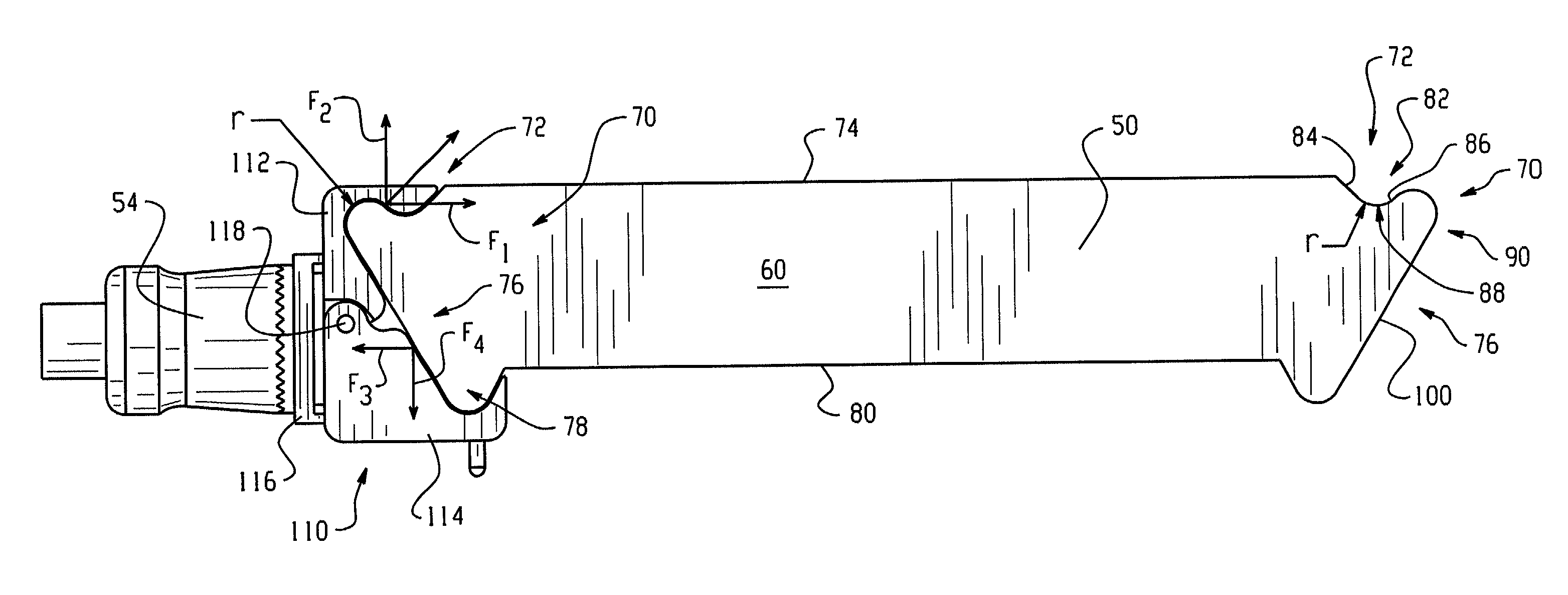
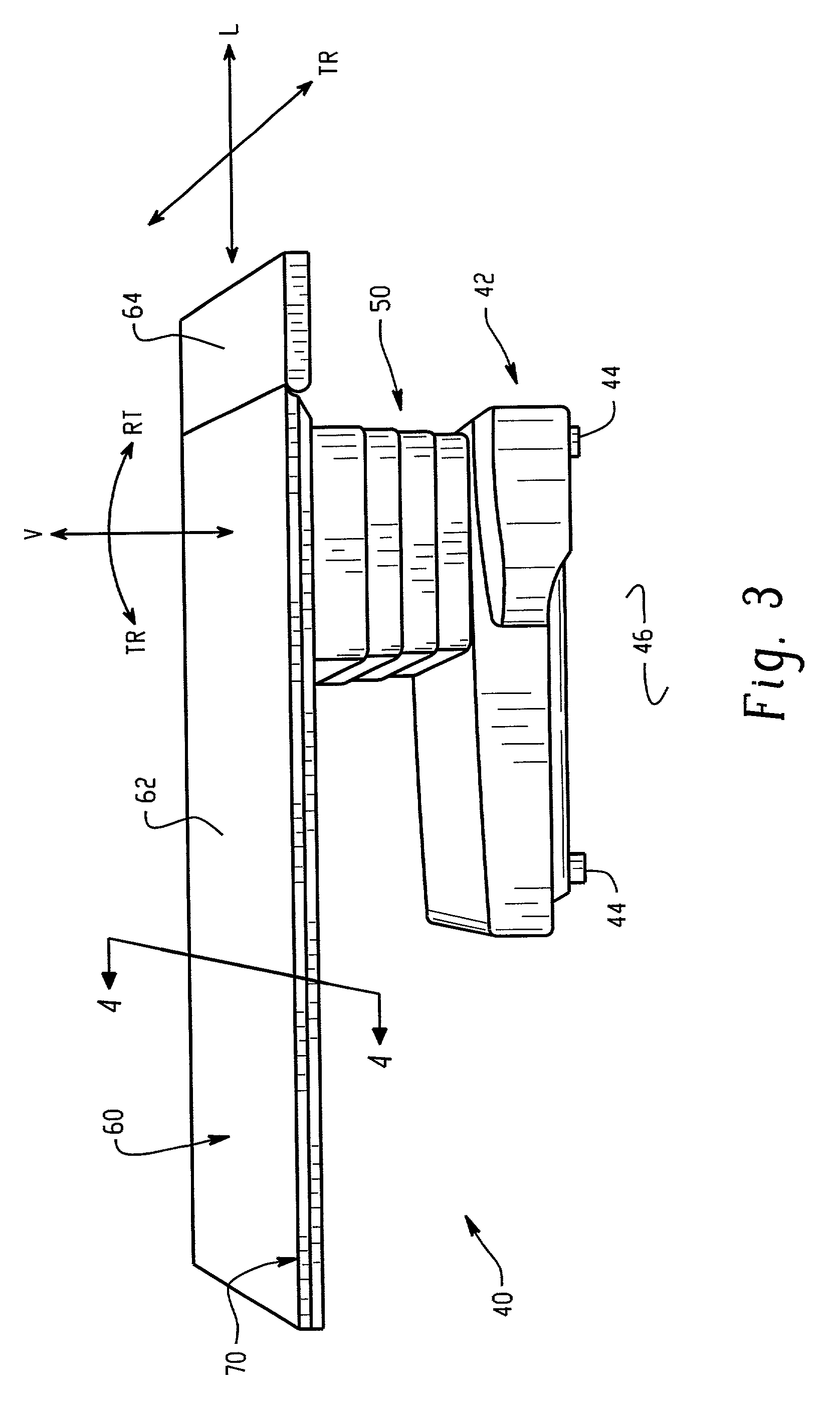
[0033]Referring now to the drawings wherein the showings are for the purposes of illustrating the preferred embodiments of the invention only and not for purposes of limiting same, FIG. 3 illustrates a floor mounted surgical table 40 with a radiolucent patient support member 60 and medical appliance support interface 70 formed in accordance with a first preferred embodiment of the invention. The table 40 has a somewhat conventional base section including a base member 42 which is supported by four legs 44, one leg 44 disposed at each corner of base member 42. The legs 44 may be of the retractable type which can be withdrawn into the base member 42 to permit wheels (not shown) to contact floor 46 and enable hospital personnel to conveniently reposition the surgical table 40 within a room. A vertical support and positioning column 50 is secured on a first lower end to the base member 42. The second or upper end of the column 50 supports the substantially planar radiolucent patient sup...


PUM


Abstract

A radiolucent surgical table (40) is provided with a low shadow accessory interface profile (70). The interface profile includes a plurality of interconnected curved surfaces formed along the entire outer edge of the patient support member for selective attachment to a range of medical accessory devices. The support interface includes a non-planar first connection area (72) having a recess (82) and a curved lip area (90) adapted to engage correspondingly formed surfaces (122, 126) on a medical accessory connector (110, 140). A second connection area (76) of the support interface (70) includes a planar locating surface (100) formed at an angle oblique with the top surface (74) of the patient support member. Engagement with the locating surface by corresponding surfaces formed on the medical accessory connectors (110, 140) generate a downward force that causes an increase in the engagement forces between the recess and lip areas of the interface and corresponding surfaces on the accessory connectors.

Description

BACKGROUND OF THE INVENTION[0001]1. Field of the Invention[0002]The present invention relates to radiolucent surgical tables and, more particularly, to a radiolucent surgical table with a low radiographic shadow edge profile used to support a patient adjacent x-ray imaging devices such as C-arm scanners, CT, fluoroscopic, and other whole body scanners.[0003]2. Description of the Prior Art[0004]Conventional surgical tables include a flat patient support and a lower base for holding the patient support a predetermined distance from the floor. The base of conventional surgical tables commonly includes control apparatus for tilting the flat patient support through a range of orientations to facilitate performance of certain surgical procedures. Typical flat patient supports are made of surgical stainless steel and in most cases include a set of metal side rails supported along the edges of the table for holding surgical accessories, instrumentation, and the like. Typically, the side rai...

Claims


Application Information

Patent Timeline
Patent Type & Authority Patents(United States)
IPC IPC(8): A61G13/10A61B5/05
CPCA61B6/0442A61G13/101F16M13/02F16M13/027F16M11/041F16M11/10F16M11/24A61B6/4423
Inventor KOLODY, TIMOTHYSANDERS, WARD L.SELIG, VICTOR M.
Owner STERIS CORP
Why Eureka
Try Eureka