Devices for adjusting the contact pressure of an adjustably mounted cylinder

a technology of adjusting cylinder and contact pressure, which is applied in the direction of printing presses, rotary presses, printing presses, etc., can solve the problems of elastic rollers being damaged by roller flexing, and achieve the effect of compact structur

Inactive Publication Date: 2006-04-04
KOENIG & BAUER AG
View PDF29 Cites 13 Cited by
  • Summary
  • Abstract
  • Description
  • Claims
  • Application Information

AI Technical Summary

Benefits of technology

[0013]A particular advantage of the fixation device of the present invention lies in that such a fixation device can be produced in an extremely compact, and therefore space-saving manner. This is achieved in that several multi-disk elements are frictionally clamped for fixing the adjustable components in place relative to each other. By the arrangement of several, and in particular a plurality, of such multi-disk elements one behind the other, the required frictional force is distributed over a plurality of frictional faces between the multi-disk elements. Because of the clamping of the multidisk elements arranged one behind the other, the clamping force acts oppositely on all frictional faces.
[0016]In principle, any arbitrary drive mechanisms, for example electrically, hydraulically or pneumatically acting systems, can be employed for actuating the spring element. It is particularly advantageous if the actuating element is embodied in the manner of a plunger which is displaceably arranged in a pressure chamber. By charging the pressure chamber with a pressure medium, such as, for example, compressed air or hydraulic fluid, the plunger can be displaced against the spring force of the spring element, so that the multi-disk elements are relaxed.
[0018]A recess is provided on the roller holder, or on the frame holder, which recess is engaged by a section of the frame holder, or of the roller holder. The dimensions of the section, or of the recess, are selected in such a way that a gap is formed between the recess and the section, by use of which gap the actuating range between the roller holder and the frame holder is defined. The roller holder can be displaced within this gap in respect to the frame holder. To be able to obtain the actuating forces required for the actuating movement, or to be able to press the first roller with a defined contact pressure against the oppositely located roller, at least one actuator is arranged in the gap, which at least one actuator exerts a pulling and / or a pushing force on the roller holder and, in the process, is supported on the frame. Because of the arrangement of the actuator in the gap between the frame holder and the roller holder, it is possible to provide extraordinarily compact structures. In this connection, it is, of course, immaterial whether the recess is provided on the frame holder or on the roller holder, so that, in principle, both constructions are alternatively conceivable.
[0022]In accordance with a preferred embodiment of the present invention, a pretensed gas, and in particular compressed air, is employed as the pressure medium. Since gases are inherently compressible, an elastic spring effect, acting between the frame holder and the roller holder, is the result of the use of a pretensed gas as the pressure medium. It is possible, because of this spring effect, to compensate for mechanical interferences caused, for example, by imbalances or out-of-roundness. Moreover, compressed air is typically available as an energy transfer source in most printing presses.
[0023]The device for setting the contact pressure between the displaceably seated roller and an oppositely located roller can also be used for placing the displaceably seated roller into contact with, or out of contact from the other roller. However, for this purpose, it is necessary to select the actuating range between the frame holder and the roller holder to be sufficiently large to be able to perform the actuating movement required for the out-of contact movement. Moreover, it is necessary to select the actuator between the frame holder and the roller holder to be suitable for performing such an actuating movement. To be able to perform the into-contact or out-of-contact movement independently of the actuation of the device, it is advantageous if the device is fastened on an additional out-of-contact device. For example, this out-of-contact device can be embodied in the manner of a pivot arm, by the use of which, the frame holder can be displaced, in relation to the frame of the printing press, between an in-contact position and out-of-contact position.
[0024]The compactness of the device in accordance with the present invention can, as a whole, be further increased by situating a fixation device in a device for adjusting the contact pressure between two rollers.

Problems solved by technology

If, for example, the contact strip in an inking unit is too narrow, not enough ink is transferred, while in the situation in which the contact strip is too broad, the elastic roller can be damaged by the roller's flexing.

Method used


Image

  • Devices for adjusting the contact pressure of an adjustably mounted cylinder
  • Devices for adjusting the contact pressure of an adjustably mounted cylinder
  • Devices for adjusting the contact pressure of an adjustably mounted cylinder

Examples


Embodiment Construction

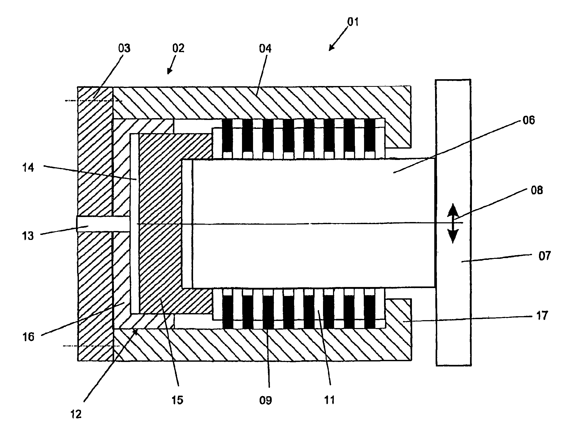
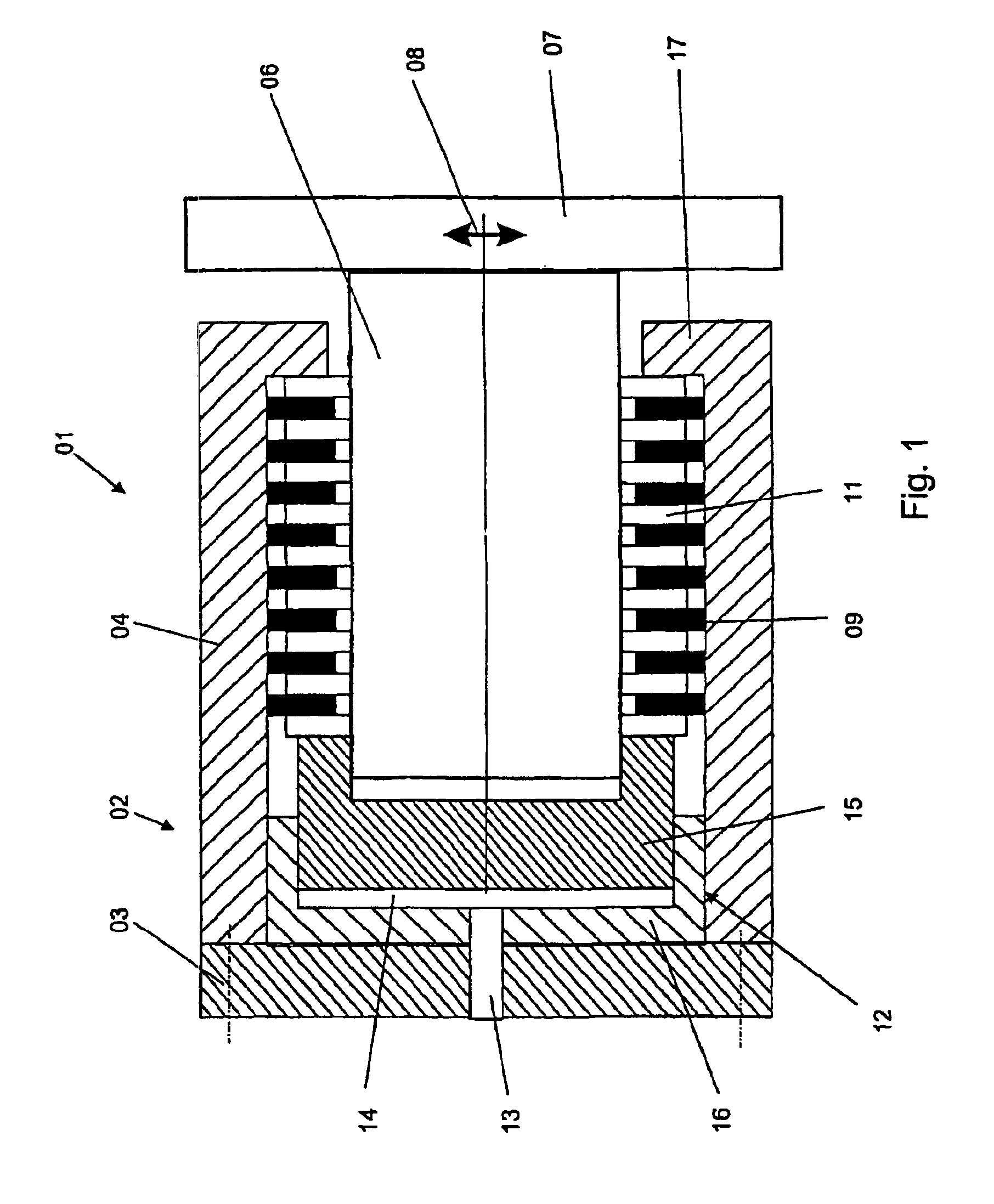
[0034]Referring initially to FIG. 1, there may be seen a fixation device, generally at 01, in accordance with the present invention. The fixation device 01 represented in FIG. 1 has an element, for example a base body 02 which is formed by a cover 03 and a sleeve 04, and an element which is displaceably seated in the sleeve 04, for example a bolt 06, on whose exterior a fastening plate 07 has been provided. The base body 02 can be fastened to a frame, for example, while a roller lock for seating a roller, for example, can be screwed to the fastening plate 07.

[0035]The bolt 06 has a defined radial play with respect to the sleeve 04, so that the bolt 06 can be displaced in relation to the base body 02 in any arbitrary actuating directions 08 in an actuating plane extending perpendicularly with respect to the drawing plane of FIG. 1. Because of this, it is possible to displace the fastening plate 07, for example upward or downward, in the direction of the movement arrow 08. Because of ...


PUM


Abstract

The contact pressure between an adjustably mounted first cylinder and a second cylinder in a printing machine, and particularly in a web-fed printing machine can be adjusted. An actuator is usable to force the first cylinder toward the second cylinder with an adjustable force. A fixing device is usable to fix the first cylinder in a desired position relative to the second cylinder.

Description

FIELD OF THE INVENTION[0001]The present invention is directed to devices for adjusting the contact pressure of a displaceably seated roller. The contact pressure is adjusted using at least one actuator. A fixation device can hold the roller in an adjusted position.BACKGROUND OF THE INVENTION[0002]A plurality of rollers are provided in conventional printing presses, for example in web-fed rotary printing presses. Inking rollers, in particular, are provided, which are used for transferring the ink from an ink reservoir to the plate cylinders. The ink transferred to the plate cylinders can be metered by the inking rollers, so that the ink is transferred as a uniform film of defined thickness. It is thus possible to even out interferences, such as speed fluctuations and rotary oscillations, for example.[0003]Moreover, dampening unit rollers, which transfer a dampening agent, for example water, to the printing group, can also be provided in the printing press.[0004]Pairs of rollers are o...

Claims


Application Information

Patent Timeline
Patent Type & Authority Patents(United States)
IPC IPC(8): B41F5/00B41F31/00B41F13/08B41F31/32B41F13/24B41F13/34B41F13/40B41F31/26B41F31/36
CPCB41F13/08B41F13/24B41F31/26B41F13/40B41F13/34
Inventor FAIST, BERND KLAUSREDER, WOLFGANG OTTOSCHNEIDER, GEORG
Owner KOENIG & BAUER AG
Why Eureka
Try Eureka