Heat exchanger

a heat exchanger and heat exchange technology, applied in the direction of lighting and heating apparatus, stationary conduit assemblies, laminated elements, etc., can solve the problems of insufficient heat exchange and hot refrigerant, and achieve the effect of further improving uniformity

Inactive Publication Date: 2006-04-04
MITSUBISHI HEAVY IND LTD
View PDF18 Cites 24 Cited by
  • Summary
  • Abstract
  • Description
  • Claims
  • Application Information

AI Technical Summary

Benefits of technology

[0013]In this heat exchanger, because the amount of refrigerant flowing into each refrigerant path is controlled by the refrigerant distribution means, the uniformity is further improved.

Problems solved by technology

However, problems such as the following can be pointed out concerning the heat exchanger having the structure described above.
However, in the conventional heat exchanger, the refrigerant supplied to the tank T passes with difficulty to the back of the tank T and there is a tendency for much of the refrigerant to flow through the upstream side of the refrigerant paths R. Thus, the flow of the refrigerant stagnates in the downstream side of the tank T. Due to this, the distribution of refrigerant to each of the refrigerant distribution parts 3 cannot be carried out uniformly, and at the refrigerant path R of the tank T positioned downstream, the refrigerant becomes hot, and the heat exchange cannot be sufficiently carried out.

Method used


Image

  • Heat exchanger
  • Heat exchanger
  • Heat exchanger

Examples


Embodiment Construction

[0024]Next, the preferred embodiments of the present invention will be explained referring to the figures.

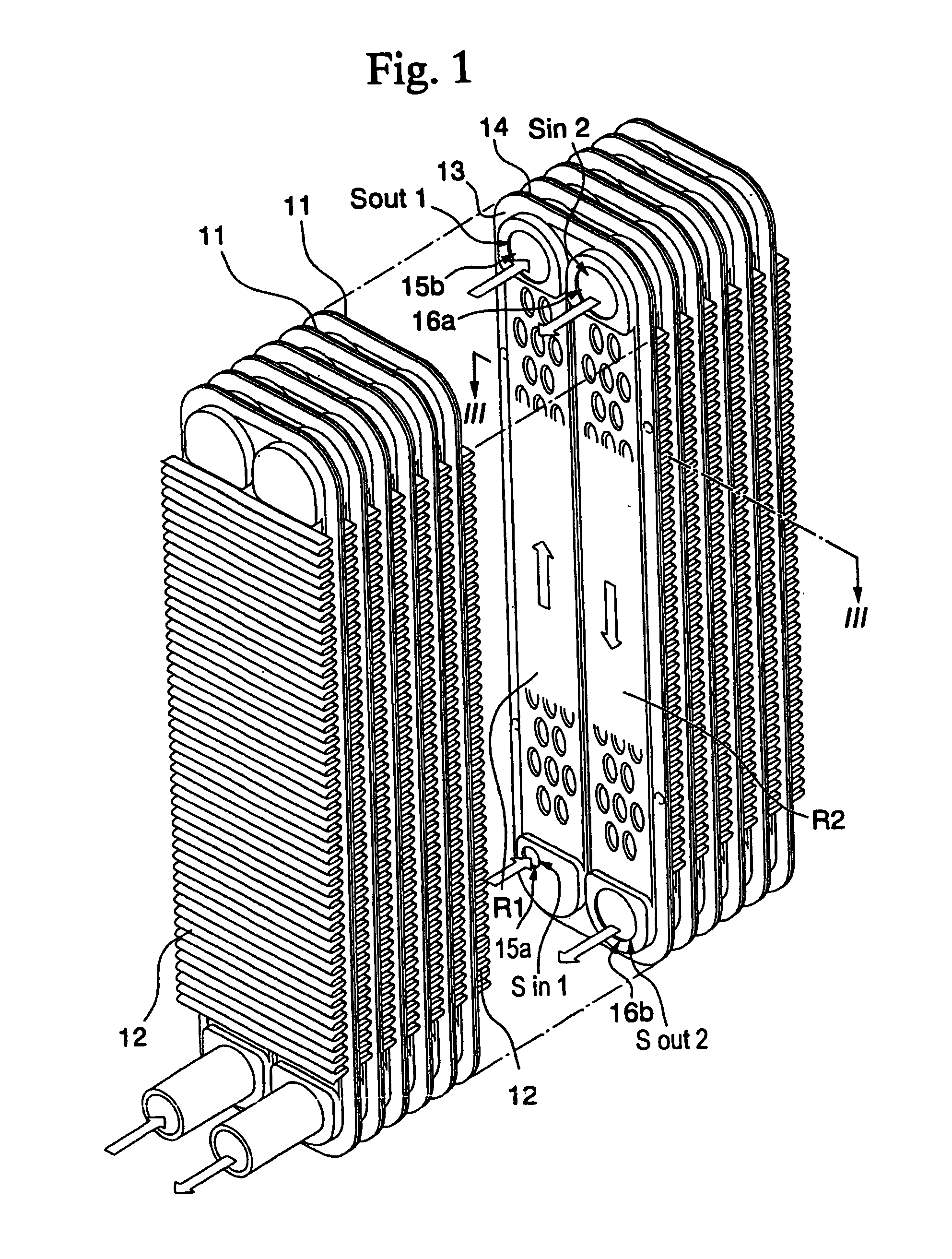
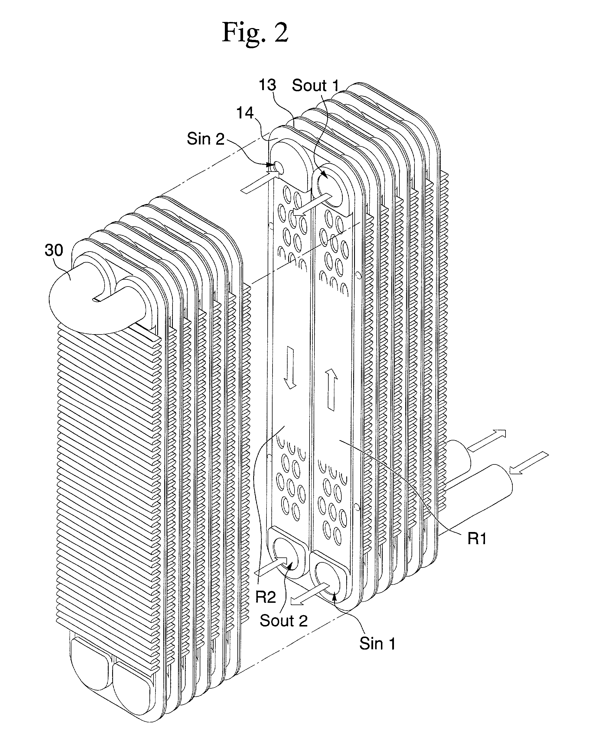
[0025]The heat exchanger shown in FIG. 1 is formed by a plate shaped refrigerant distribution part 11 and a wave shaped refrigerant fin 12 being alternatively layered. FIG. 2 is a perspective drawing of the heat exchanger seen from the back side.

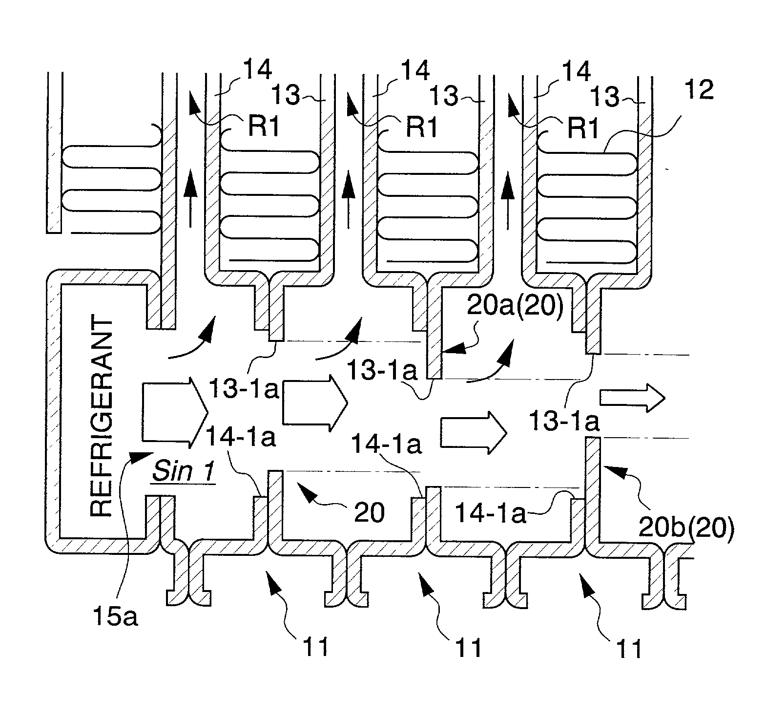
[0026]As also shown in FIG. 5, the refrigerant distribution part 11 comprises substantially rectangular plates 13 and 14, which have been drawing processed, being layered and brazed at the periphery and center. In the refrigerant distribution part 11, independent refrigerant paths R1 and R2 through which the refrigerant flows are provided next to each other. In the lower part, the refrigerant entrance 15a and the refrigerant exit 16b of the refrigerant paths R1 and R2 are provided next to each other. In the upper part, refrigerant exit 15b and refrigerant entrance 16a of the respective refrigerant paths R1 and R2 are provided next to eac...


PUM


Abstract

The invention has as an object providing a two-block heat exchanger that can improve the heat exchange capacity by distributing the refrigerant evenly in the refrigerant path. The invention is a two-block heat exchanger, and the refrigerant distribution part provides two separate refrigerant paths R1 and R2 through which the refrigerant flows and an opening provided at both of the respective ends of these refrigerant paths R1 and R1. Among the two refrigerant paths R1 and R2, the open end of the space Sout 1 (refrigerant circulation space) on the exit side formed by the one opening of the one refrigerant path R1 is connected to the open end of the space Sin 2 (refrigerant circulation space) on the entrance side formed by one opening of the other refrigerant path R2. After the refrigerant flows into the refrigerant path R1 of each refrigerant distribution part, and refrigerant flows through the refrigerant path R2 of each of the refrigerant distribution parts.

Description

BACKGROUND OF THE INVENTION[0001]1. Field of the Invention[0002]The present invention relates to a heat exchanger mounted on an air conditioning device and the like.[0003]2. Description of the Related Art[0004]FIG. 9 shows an example of a two-block heat exchanger used as an evaporator in an automobile air conditioning system and the like. The heat exchanger shown in the figure is referred to as a drawn cup type, and is formed by plate-shaped refrigerant distribution parts 3 comprising overlapping rectangular plates 1 and 2 that have had a drawing process carried out thereon and cooling fins 4 bent into an wave shape being alternately layered.[0005]In the refrigerant distribution parts 3, the periphery and center of the plates 1 and 2 are brazed, and thereby a U-shaped refrigerant path R is formed that goes from the refrigerant entrance 5 provided at the top, descending to and returning from the bottom for discharge into the refrigerant exit 6 provided at the top and arranged next to...

Claims


Application Information

Patent Timeline
Patent Type & Authority Patents(United States)
IPC IPC(8): F28D1/03F28F9/22F28F3/08F28F9/26F28F13/08F28F27/02
CPCF28F9/028F28D1/0333
Inventor SAITO, KATSUHIROINOUE, MASASHI
Owner MITSUBISHI HEAVY IND LTD
Why Eureka
Try Eureka