Methods of downhole testing subterranean formations and associated apparatus therefor

a subterranean formation and subsurface technology, applied in the field of operations, can solve the problem of unnecessary perforation step

Inactive Publication Date: 2006-04-04
HALLIBURTON ENERGY SERVICES INC
View PDF48 Cites 28 Cited by
  • Summary
  • Abstract
  • Description
  • Claims
  • Application Information

AI Technical Summary

Benefits of technology

[0008]In another aspect of the present invention, a method includes steps wherein fluids from a first formation are flowed into a tubular string installed in the well, and the fluids are then disposed of by injecting the fluids into a second formation. The disposal operation may be performed by alternately applying flu

Problems solved by technology

Of course, if the well is uncased,

Method used


Image

  • Methods of downhole testing subterranean formations and associated apparatus therefor
  • Methods of downhole testing subterranean formations and associated apparatus therefor
  • Methods of downhole testing subterranean formations and associated apparatus therefor

Examples


Embodiment Construction

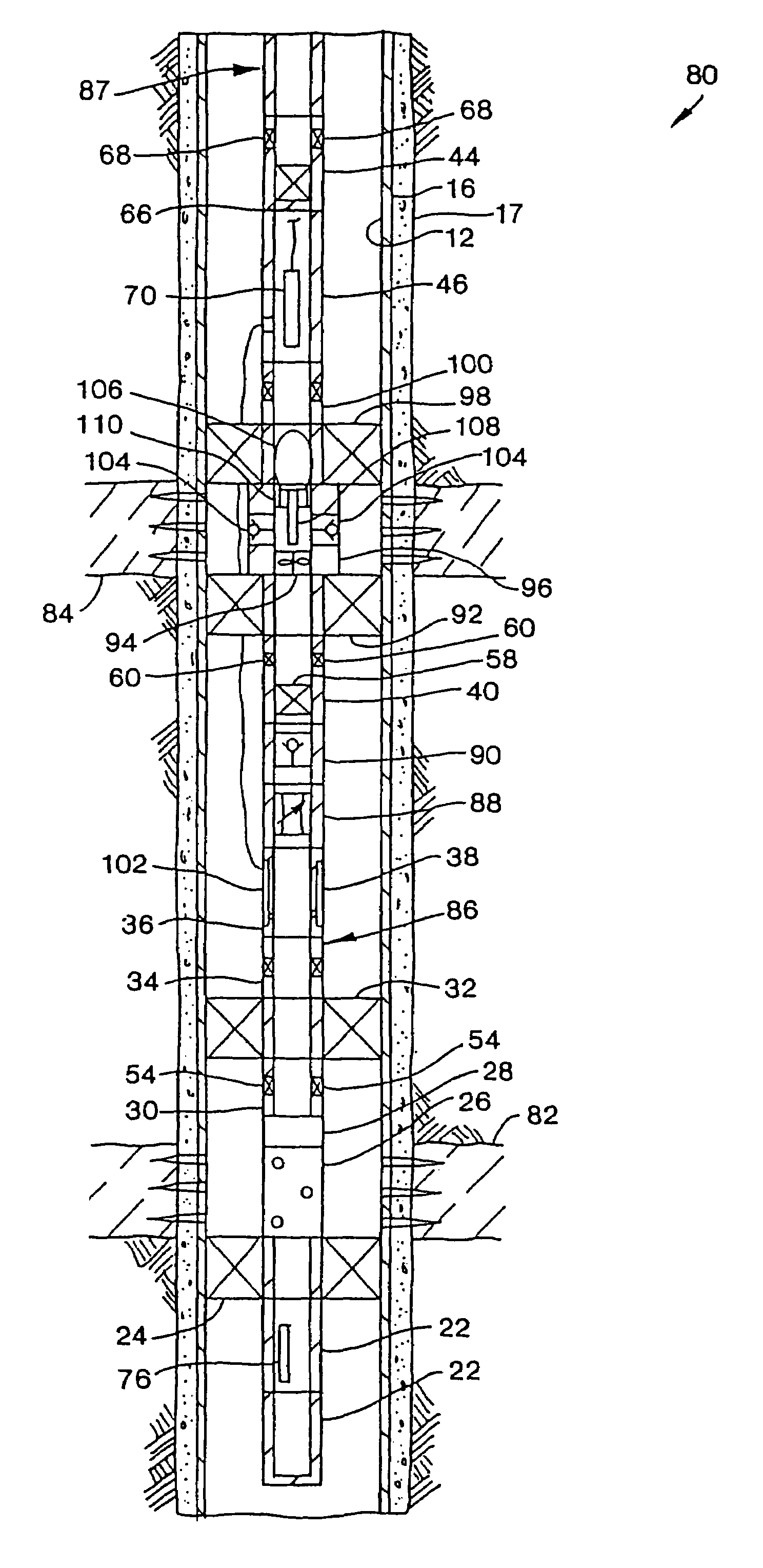
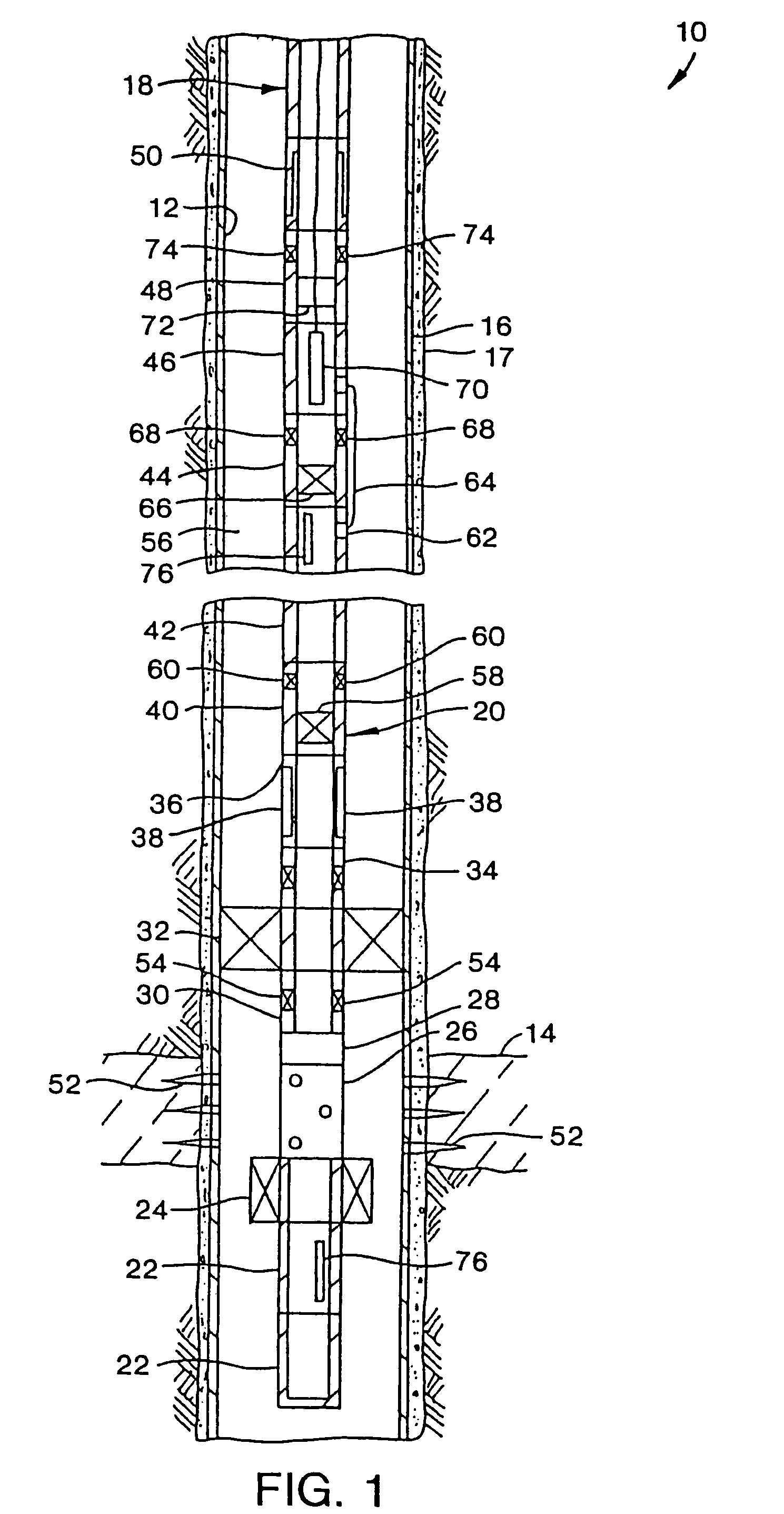
[0018]Representatively illustrated in FIG. 1 is a method 10 which embodies principles of the present invention. In the following description of the method 10 and other apparatus and methods described herein, directional terms, such as “above”, “below”, “upper”, “lower”, etc., are used for convenience in referring to the accompanying drawings. Additionally, it is to be understood that the various embodiments of the present invention described herein may be utilized in various orientations, such as inclined, inverted, horizontal, vertical, etc., without departing from the principles of the present invention.

[0019]In the method 10 as representatively depicted in FIG. 1, a wellbore 12 has been drilled intersecting a formation or zone of interest 14, and the wellbore has been lined with casing 16 and cement 17. In the further description of the method 10 below, the wellbore 12 is referred to as the interior of the casing 16, but it is to be clearly understood that, with appropriate modif...


PUM


Abstract

Methods and apparatus are provided which permit well testing operations to be performed downhole in a subterranean well. In various described methods, fluids flowed from a formation during a test may be disposed of downhole by injecting the fluids into the formation from which they were produced, or by injecting the fluids into another formation. In several of the embodiments of the invention, apparatus utilized in the methods permit convenient retrieval of samples of the formation fluids and provide enhanced data acquisition for monitoring of the test and for evaluation of the formation fluids.

Description

CROSS-REFERENCE TO RELATED APPLICATIONS[0001]The present application is a division of application Ser. No. 10 / 270,424 filed Oct. 11, 2002, now U.S. Pat. No. 6,729,398 which was a continuation of application Ser. No. 09 / 971,205 filed Oct. 4, 2001, now U.S. Pat. No. 6,527,052, which was a division of application Ser. No. 09 / 378,124 filed Aug. 19, 1999, now U.S. Pat. No. 6,325,146, which claims the benefit of the Mar. 31, 1999 filing date of provisional application Ser. No. 60 / 127,106. The disclosure of each of these earlier applications is incorporated herein in its entirety by this reference.BACKGROUND OF THE INVENTION[0002]The present invention relates generally to operations performed in conjunction with subterranean wells and, in an embodiment described herein, more particularly provides a method of performing a downhole test of a subterranean formation.[0003]In a typical well test known as a drill stem test, a drill string is installed in a well with specialized drill stem test e...

Claims


Application Information

Patent Timeline
IPC IPC(8): E21B49/00E21B21/00E21B41/00E21B43/119E21B49/08
CPCE21B21/002E21B41/0057E21B43/119E21B49/088E21B49/081E21B49/082E21B49/084E21B43/129
Inventor RINGGENBERG, PAUL DAVIDPROETT, MARK ANTONPELLETIER, MICHAEL T.HINZ, MICHAEL L.GILBERT, GREGORY N.NIVENS, HAROLD WAYNEAZARI, MEHDI
Owner HALLIBURTON ENERGY SERVICES INC
Why Eureka
Try Eureka