Vehicle shipping rack and related methods

a technology for vehicles and racks, applied in the field of vehicles shipping racks, can solve the problems of not being able to easily move the rack, not being able to protect the associated motorcycle from damage from external sources, and not being able to protect the adjacent motorcycle from damage, etc., and achieve the effect of facilitating the movement of the rack and the motorcycl

Inactive Publication Date: 2006-04-04
KEYBOARD CARRIAGE
View PDF19 Cites 25 Cited by
  • Summary
  • Abstract
  • Description
  • Claims
  • Application Information

AI Technical Summary

Benefits of technology

[0022]In accordance with a sixth aspect of the invention, a method of retrofitting an existing motorcycle shipping rack is disclosed. The method comprises pivotally mounting a protective assembly including an upstanding post along at least two different sides of the rack and pivotally mounting a plurality ...

Problems solved by technology

First of all, nothing on the rack guards or protects the associated motorcycle against damage from external sources, including adjacent motorcycles, racks, or other structures that may be encountered during shipping.
Any resulting damage is typically the responsibility of the common carrier, and can be a significant source of loss.
Secondly, no manner of easily moving the rack, including with the motorcycle in the mounted condition, is provided.
As should be appreciated, this is extraordinarily difficult to accomplish in the confines of the trailer, especially when the rack is surrounded by other racks or cargo.
As can be readily appreciated, the deleterious complexity of this operation significantly increases the overall shipping cost, and can further increase the chances of ...

Method used


Image

  • Vehicle shipping rack and related methods
  • Vehicle shipping rack and related methods
  • Vehicle shipping rack and related methods

Examples


Embodiment Construction

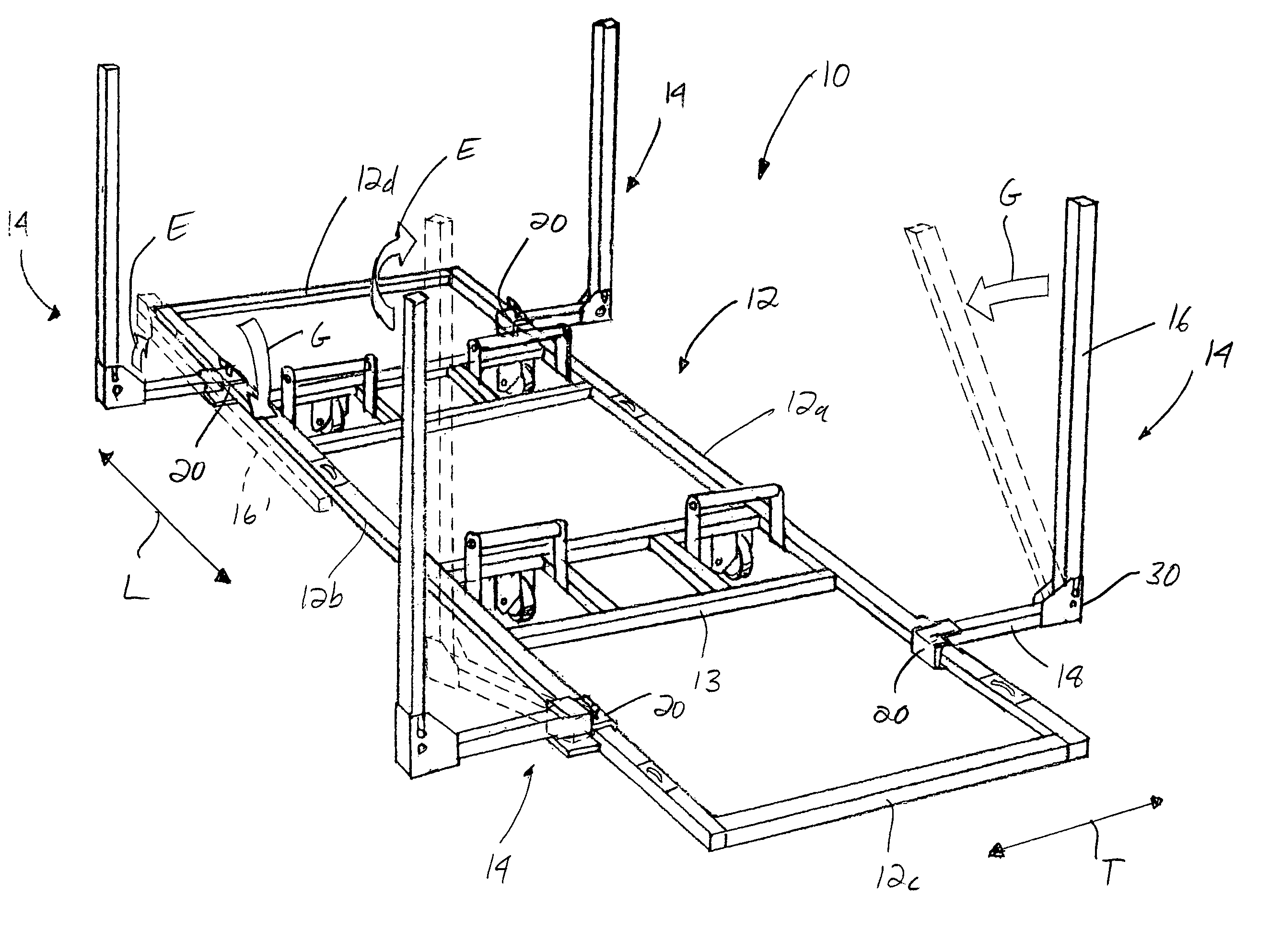
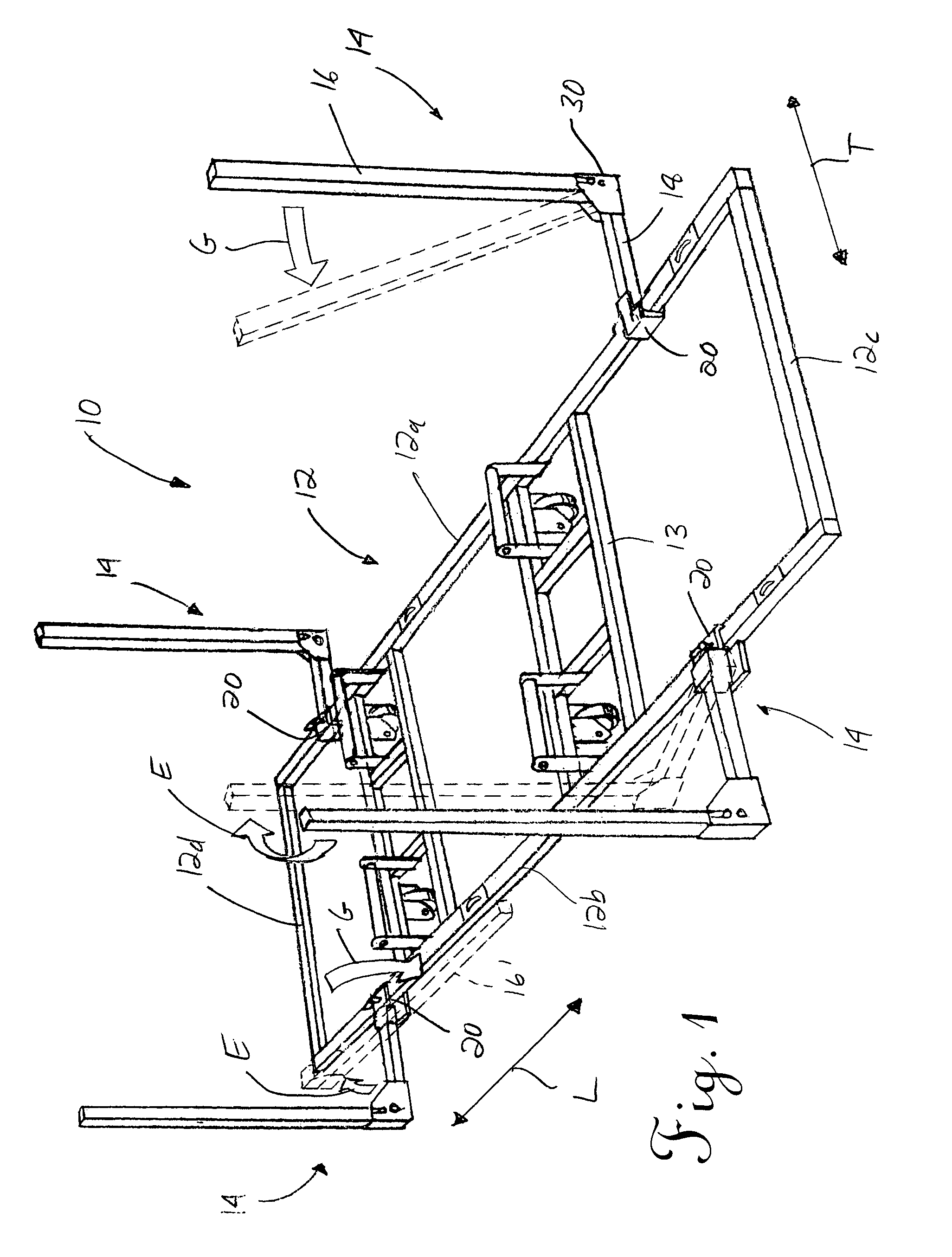
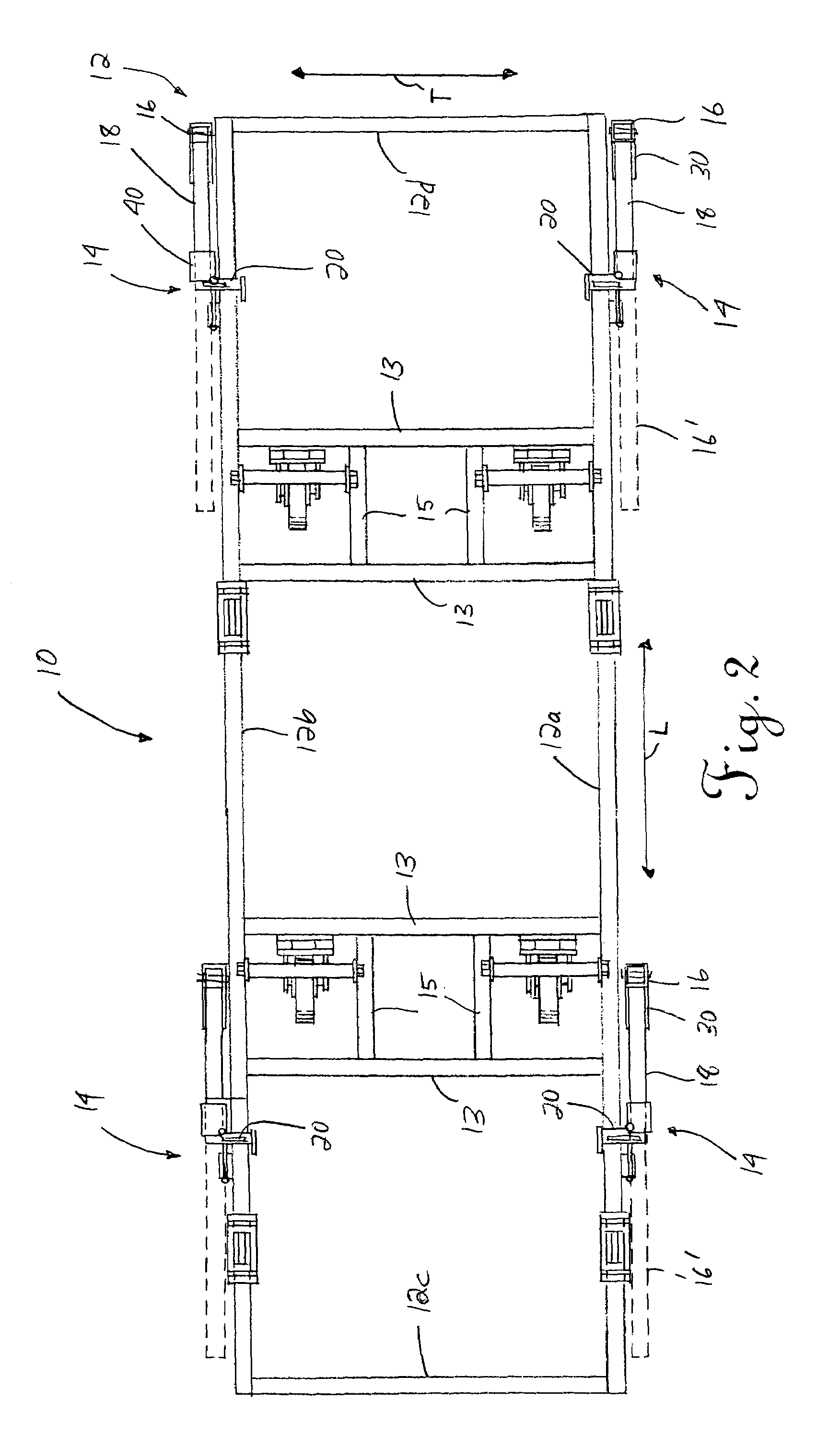
[0042]Reference is now made to FIGS. 1 and 2, which comprise, respectively, an overall perspective view and an overall top plan view of one possible embodiment of the improved shipping rack 10 of the present invention. In this embodiment, the rack 10 includes a base in the form of a generally rectangular frame 12. The frame 12 thus includes first and second, generally opposed, elongated sides 12a, 12b defining a longitudinal direction L, as well as third and fourth, generally opposed shorter sides 12c, 12d defining a transverse direction T.

[0043]As should be appreciated, the frame 12 may be comprised of interconnected pieces of tubular bar stock, which are preferably formed of a durable metal such as steel. Conventional techniques, such as welding, may be used to secure the pieces together to form the frame 12. The pieces are preferably of suitable dimensions to form the frame 12 such that it is adapted for receiving and supporting a vehicle, such as a motorcycle M (not shown in FIG...


PUM


Abstract

Disclosed is a rack for supporting a vehicle, such as a motorcycle, during shipping. In one embodiment, the rack includes selectively actuated support assemblies, each having a rotatably mounted wheel. In the actuated position, the wheels facilitate movement of the rack and vehicle together. In this and possibly another embodiment, the rack includes a protective assembly having an upstanding guard mounted on opposed sides of a base in the form of a generally rectangular frame. Each protective assembly with the upstanding guard may move between a first, retracted position adjacent to the corresponding side of the frame and a second, extended position farther away from that side of the frame. The guard is also collapsible, including when the protective assembly is in the retracted position, to provide the rack with a low profile when not in use. Related methods are also disclosed, including a method of retrofitting an existing shipping rack to include the disclosed protective and support assemblies.

Description

TECHNICAL FIELD[0001]This invention relates generally to the vehicle shipping and transportation arts and, more particularly, to an improved rack for intended use in the course of shipping a wheeled vehicle, such as a motorcycle.BACKGROUND OF THE INVENTION[0002]Various types of racks for use in shipping vehicles such as motorcycles are known in the art. A typical modern arrangement is illustrated in U.S. Pat. No. 5,133,453 to Fritze, and includes a base supporting a ramped center receiver or guide channel adapted for receiving the wheels of the motorcycle. Once the motorcycle is in the appropriate position on the rack, hold down straps maintain the motorcycle in the upright position (which is usually the desired orientation for shipping). During the unloading sequence, the straps are simply released and the motorcycle is backed through the channel, down the ramp, and onto the ground.[0003]Although the arrangement in the Fritze patent facilitates the loading and unloading the motorcy...

Claims


Application Information

Patent Timeline
IPC IPC(8): B65D85/68A47F7/00B60P7/08
CPCB60P3/07B65D85/68B65D2585/6867
Inventor ROBEY, DENNIS P.
Owner KEYBOARD CARRIAGE
Why Eureka
Try Eureka