
Eureka
For R&D, Eureka makes reading and utilizing patents & technical documents easy.
Eureka AIR
Designed for self-driven R&D workflows. Generate viable solutions, solve complex R&D challenges, empower your innovation with AI.

Eureka Materials
Designed for material experts only. Revolutionize your material R&D, from search, analyze, to developing new materials.

TechResearch
Generate reliable direction feasibility study reports for your R&D in just a few steps.

TechSeek
Discover and master advanced knowledge NOW. Basics, ideas, possibilities, all at once.

TechMind
As an expert in R&D Theories, TechMind can generates customized viable solutions instantly.

TechRisk
Analyze your overall solution with one click, know your potential R&D risks in advance.

TechMonitor
Get weekly tech updates, stay abreast of the latest tech innovations and key insights.
Fuel injection device having injection hole plate
- Summary
- Abstract
- Description
- Claims
- Application Information
AI Technical Summary
Benefits of technology
Problems solved by technology
Method used
Image

Examples
first embodiment
(First Embodiment)
[0034]A first embodiment of the present invention will be described with reference to the accompanying drawings.
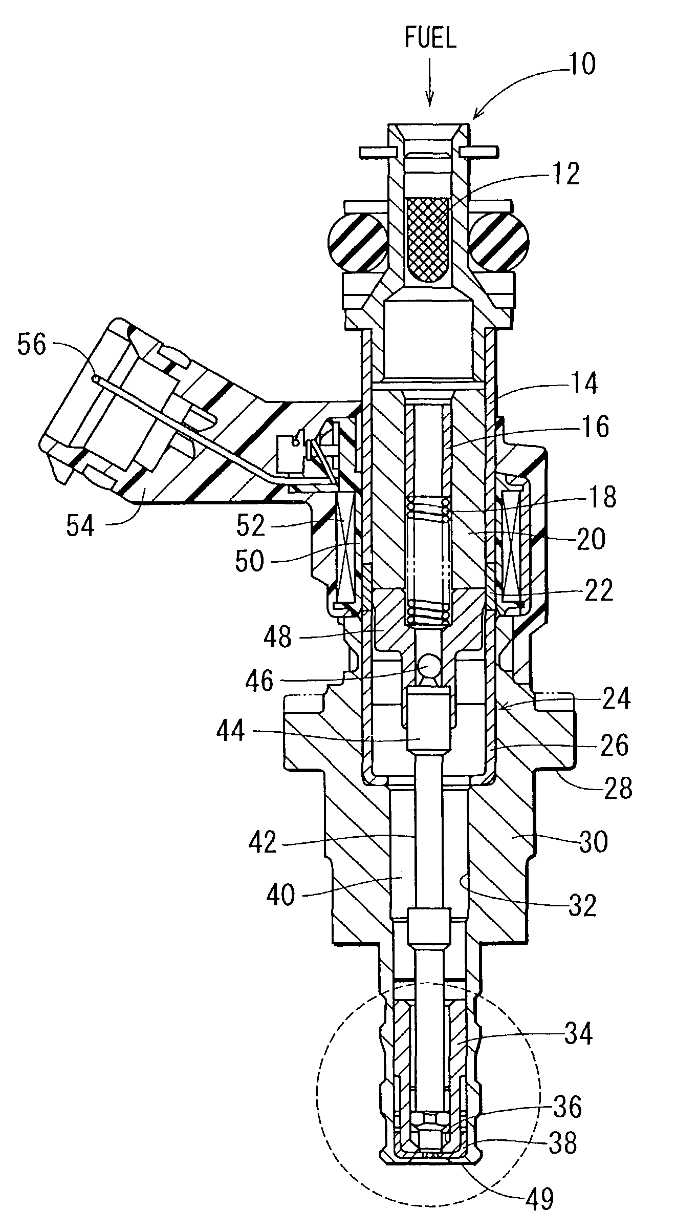
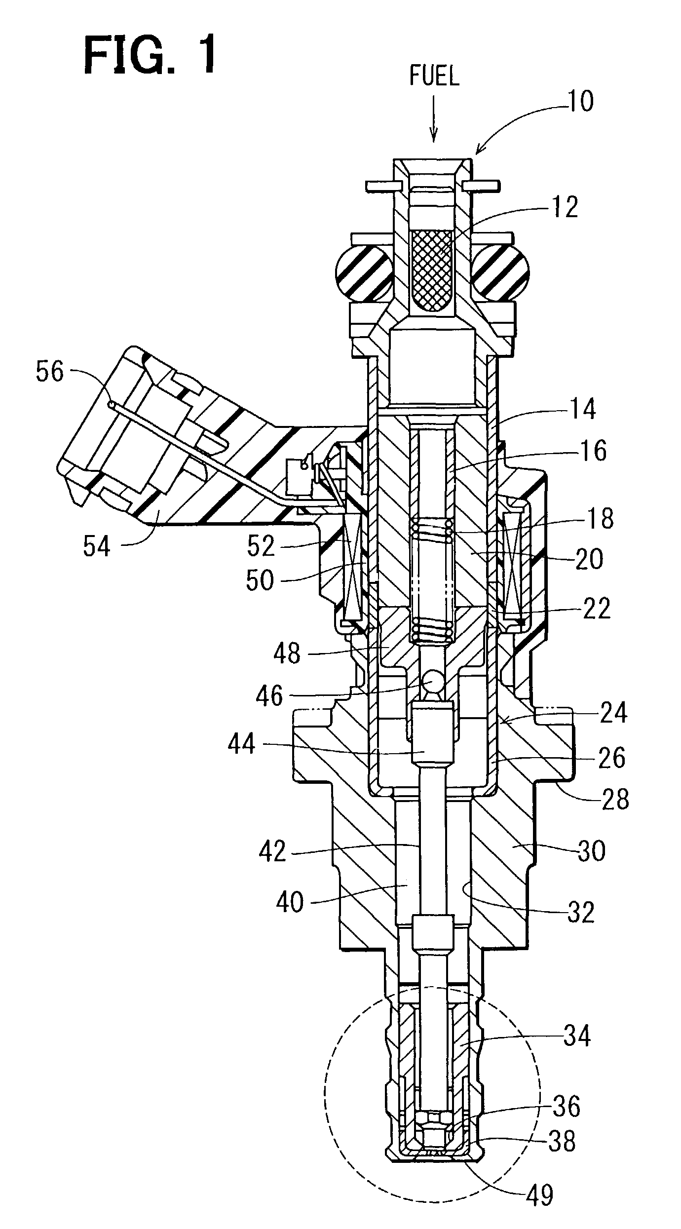
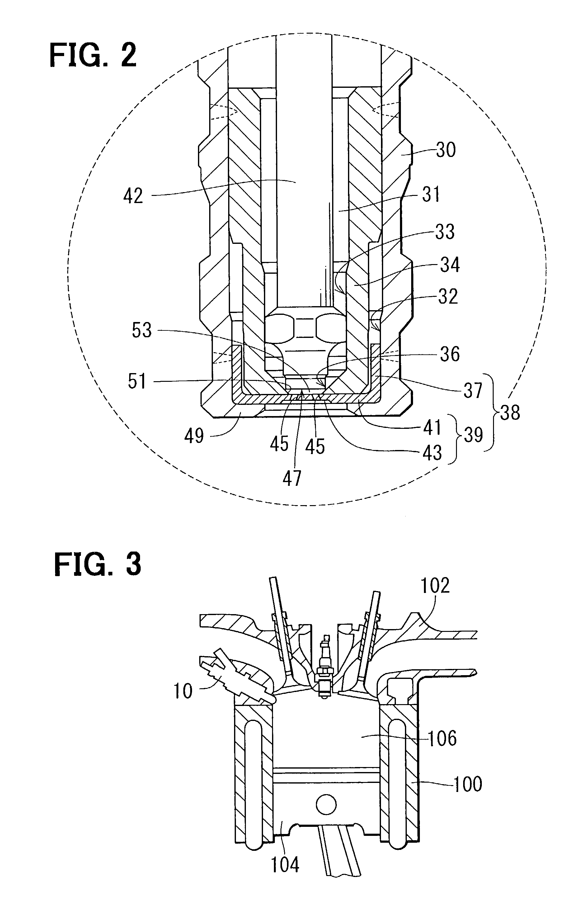
[0035]FIG. 1 is a cross sectional view of a fuel injection device (also referred to as an injector) 10 according to a first embodiment of the present invention, and FIG. 2 is a partially enlarged view of the fuel injection device 10. FIG. 3 is a cross sectional view showing an installation position of the fuel injection device 10.
[0036]In the present embodiment, with reference to FIG. 3, the fuel injection device 10 is a fuel injection device for a gasoline engine of a direct injection type, which directly injects fuel into a combustion chamber 106 of the gasoline engine. The fuel injection device 10 is installed to a cylinder head 102, which surrounds the combustion chamber 106. It should be understood that the present invention can be alternatively embodied in another fuel injection device, which injects fuel into an intake pipe. Furthermore, the presen...
second embodiment
(Second Embodiment)
[0053]FIGS. 6 and 7 show a fuel injection device according to a second embodiment of the present invention. With reference to FIG. 8, a fuel injection device 210 according to the second embodiment is installed to a cylinder head 204, which surrounds a combustion chamber 202 of a gasoline engine, and is a direct injection type, which directly injects fuel into the combustion chamber 202.
[0054]As shown in FIG. 6, a housing 211 is formed into a cylindrical shape. The housing 211 includes a first magnetic portion 212, a non-magnetic portion 213 and a second magnetic portion 214, which are coaxially arranged. The non-magnetic portion 213 prevents magnetic short circuit between the first magnetic portion 212 and the second magnetic portion 214. A stationary core 215 is made of a magnetic material and is shaped into a cylindrical body. Also, the stationary core 215 is secured coaxially with the housing 211 at a location radially inward of the housing 211. A movable core ...
third embodiment
(Third Embodiment)
[0067]FIG. 11 shows a fuel injection device according to a third embodiment of the present invention. Components similar to those discussed with reference to the second embodiment will be indicated by the same numerals.
[0068]In the fuel injection device 250 of the third embodiment, a thick wall portion 252, which has a wall thickness thicker than that of the nozzle portion 231 provided with the injection holes 229, is formed in an outer section of the planar wall 228, which is located radially outward of the nozzle portion (inner section) 231 in the planar wall 228 of the injection hole plate 226. The thick wall portion 252 has a generally annular lateral cross section, which extends circumferentially about the axis O. A recessed groove 254 is provided in a radially intermediate section of the thick wall portion 252 and is opened in an outer wall surface 228b of the planar wall 228. The groove 254 is an annular groove that extends continuously in the circumferentia...
PUM
 Abstract
Description
Claims
Application Information
 - R&D Engineer
- R&D Manager
- IP Professional
- Industry Leading Data Capabilities
- Powerful AI technology
- Patent DNA Extraction
Browse by: Latest US Patents, China's latest patents, Technical Efficacy Thesaurus, Application Domain, Technology Topic, Popular Technical Reports.
© 2024 PatSnap. All rights reserved.Legal|Privacy policy|Modern Slavery Act Transparency Statement|Sitemap|About US| Contact US: help@patsnap.com