Waste pulping system

a pulping system and waste technology, applied in the direction of gas current separation, supporting apparatus, manufacturing tools, etc., can solve the problems of vibration transmission between the pulping tank and its surroundings, the effect of reducing the efficiency of the system

Inactive Publication Date: 2006-04-04
PREMARK FEG L L C
View PDF2 Cites 0 Cited by
  • Summary
  • Abstract
  • Description
  • Claims
  • Application Information

AI Technical Summary

Benefits of technology

[0015]In accordance with the present invention, an impeller assembly for a waste pulping apparatus is provided, the impeller assembly including a rotating blade for pulping the waste to form a slurry, the rotating blade having an axis of rotation, a base and a plurality of ears that axially extend away from the base. The impeller assembly also includes a sieve ring having axially opposed first and second ends, an inner cylindrical surface and an outer cylindrical surface. The sieve ring encircling the base of the rotating blade at the first end. At least a portion of the ears are radially spaced inside the inner cylindrical surface so that the ears rotate within the sieve ring. A plurality of pumping vanes are also provided for pumping the slurry, where each pumping vane has a pumping surface that rotates radially outside the outer cylindrical surface of the sieve ring. Preferably, the pumping vanes can be easily changed to allow for various head condition while providing a predetermined pumping capacity.

Problems solved by technology

A problem that can occur with pulpers is the buildup of fibrous debris at the sieve ring or rotating blades.
This buildup, also known as “bridging” or “log jamming,” can cause blockage of the sieve ring that can back up the pulping system which can have a negative impact on the pulping efficiency of the system.
Another problem associated with many pulpers is the translation of vibrations between the pulping tank and its surroundings, particularly to the frame of the pulper.
As the pulper is used, vibration is translated to the frame from the tank, and then to the table, causing the dishes to vibrate.
This can be very noisy as the dishes vibrate and clatter.
This is very undesirable for the restaurant, as it is annoying and distracting to the customers and the employees.
Yet another problem that can occur with pulpers has to do with the feed tray.
Many pulping systems operate at a flow rate which results in a turbulent, splashing flow of the return water within the feed tray.
This would also be undesirable because the mess must be cleaned up repeatedly.

Method used


Image

  • Waste pulping system
  • Waste pulping system
  • Waste pulping system

Examples


Embodiment Construction

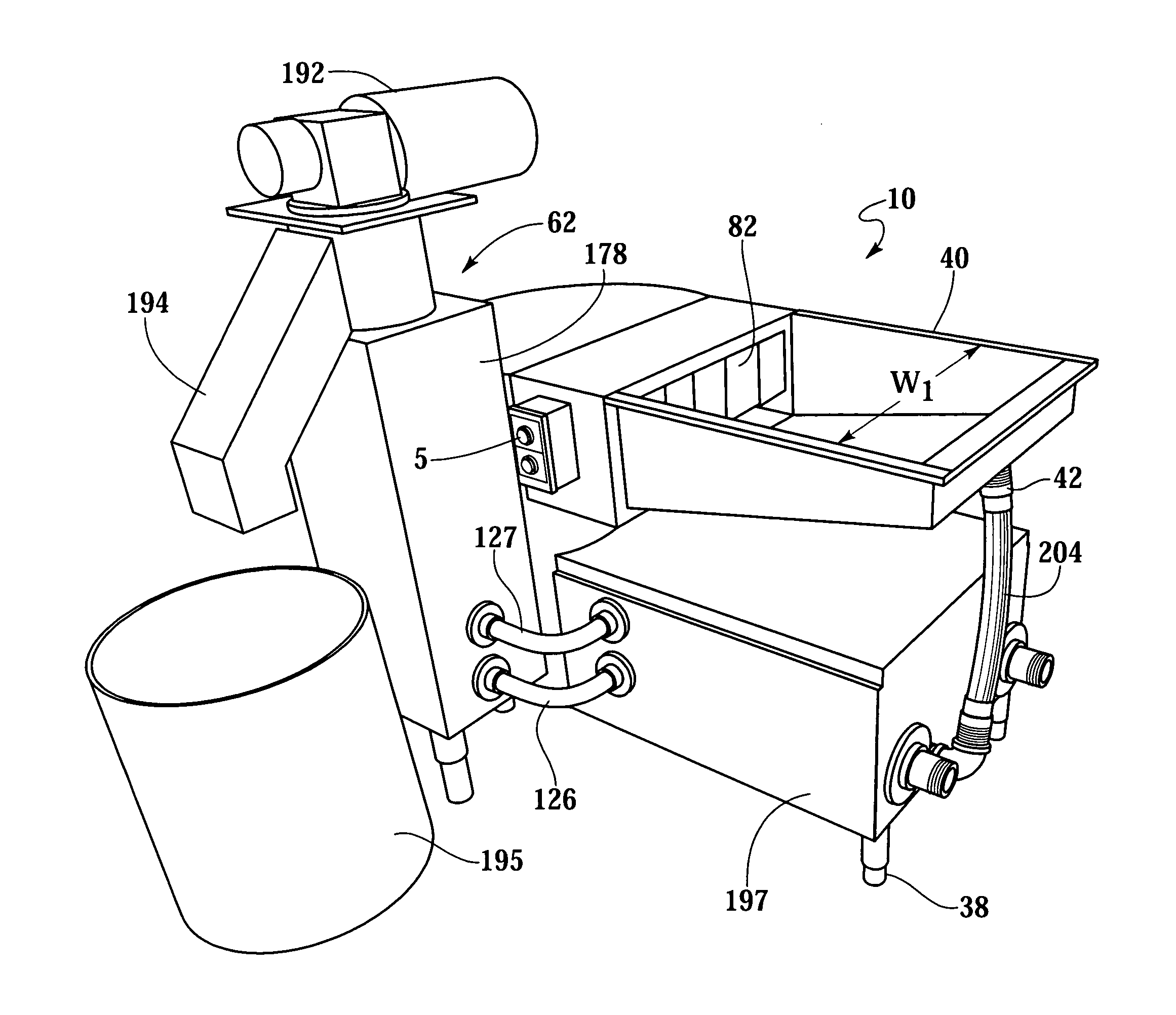
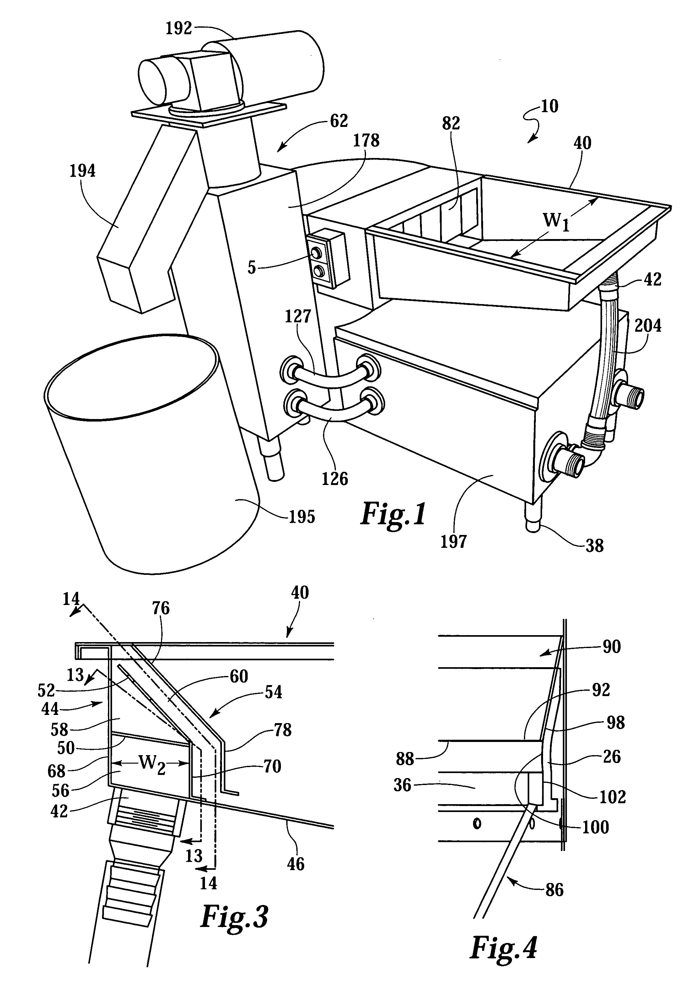
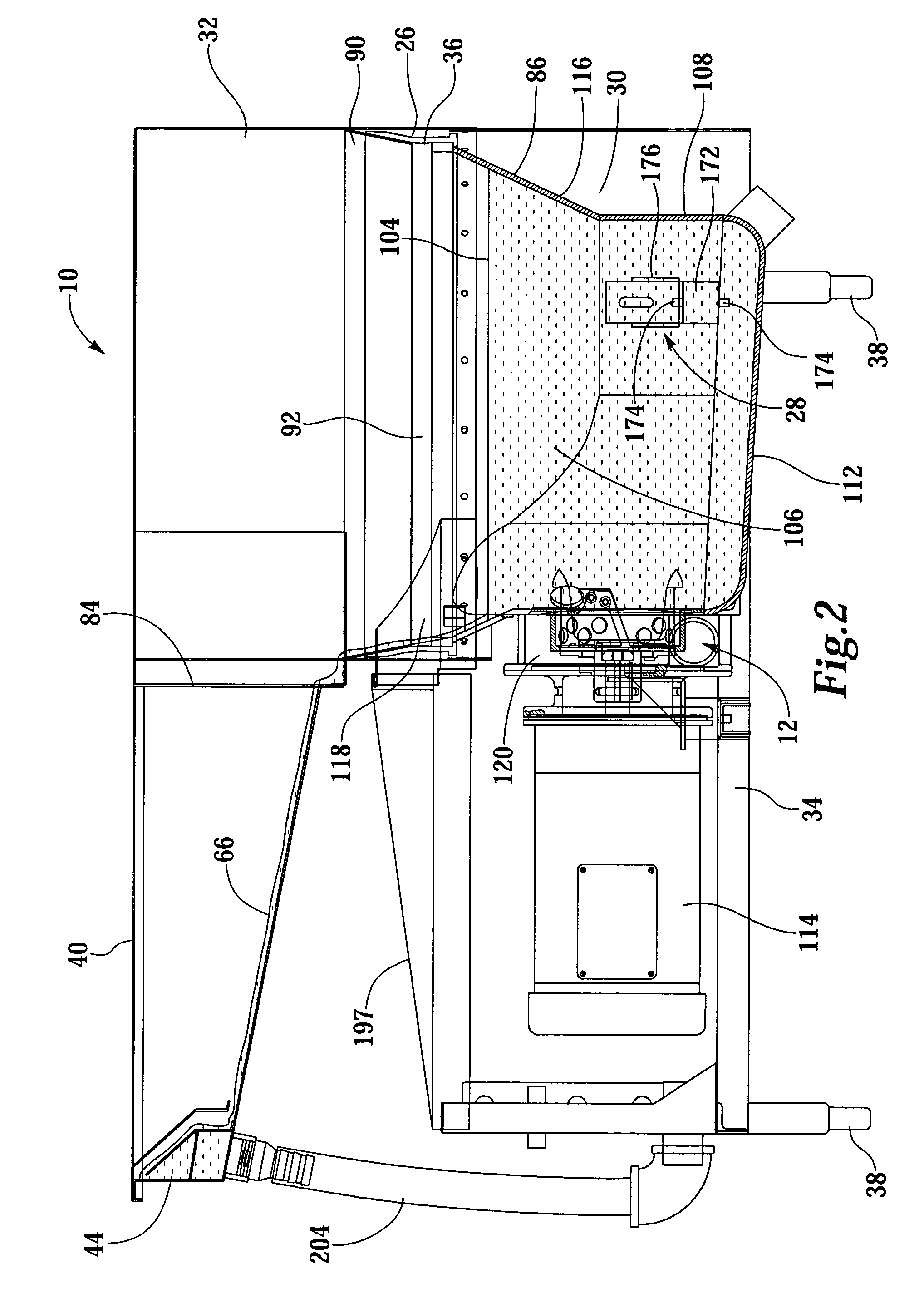
[0040]FIGS. 1 and 2 show overall views of a novel and improved pulping system 10 provided by the present invention for the pulping of solid waste material. The inventive pulping system 10 includes a pulping tank 30 and a novel and improved cutting mechanism 12, as shown in more detail in FIGS. 5, 6 and 7, which includes an impeller 14, a rotating blade 16, a sieve ring 18, stationary blades 20, interrupter bars 22, and pumping vanes 24. Pumping vanes 24 can be modularly changed to provide for different desired pumping capacities. Cutting mechanism 12 is also known as an impeller assembly. Cutting mechanism 12 is connected to a driving motor 114, which provides the energy for grinding waste into a slurry and the energy for pumping the slurry. Motor 114 is activated by a set of controls 5 on pulping system 10, see FIG. 1. Pulping system 10 is supported by a frame 34 and a set of supporting feet 38.

[0041]Pulping system 10 also includes a vibration seal 26 and a set of vibration mountin...


PUM

PropertyMeasurementUnit
distanceaaaaaaaaaa
diameteraaaaaaaaaa
diameteraaaaaaaaaa

Abstract

In a waste pulping apparatus, an impeller assembly comprises a rotating blade for pulping solid waste to form a slurry, the rotating blade having an axis of rotation, a base and a plurality of ears that axially extend away from the base. The impeller assembly also includes a sieve ring having axially opposed first and second ends, an inner cylindrical surface and an outer cylindrical surface, where the sieve ring encircles the base of the rotating blade at the first end so that a portion of the ears are radially spaced inside the inner cylindrical surface so that the ears rotate within the sieve ring. A plurality of pumping vanes are also provided for pumping the slurry, where each pumping vane has a pumping surface that rotates radially outside the outer cylindrical surface of the sieve ring. Preferably, the pumping vanes can be easily changed to allow for various head condition while providing a predetermined pumping capacity.

Description

[0001]This application is a division of U.S. patent application Ser. No. 10 / 145,473, filed May 14, 2002 now U.S. Pat. No. 6,776,365, which claims the benefit of U.S. Provisional Application No. 60 / 363,679, filed on Mar. 12, 2002.BACKGROUND OF THE INVENTION[0002]1. Field of the Invention[0003]The present invention is directed to an apparatus for disintegrating solid waste to form a pulp for disposal.[0004]2. Description of the Related Art[0005]Waste reduction systems such as solid waste pulpers have been in use for many years. One such system is disclosed in Altonji et al., U.S. Pat. No. 5,577,674, assigned to the assignee of this application, the disclosure of which is incorporated herein by reference. In typical systems such as that in U.S. Pat. No. 5,577,674, waste from a kitchen or another waste source is placed into a pulping tank partially filled with water. A cutting or grinding mechanism is installed near the bottom of the tank and usually includes a rotating impeller with at...

Claims


Application Information

Patent Timeline
Patent Type & Authority Patents(United States)
IPC IPC(8): B02C23/36D21B1/34
CPCB02C18/0092D21B1/347D21B1/345B02C23/36
Inventor ENO, STEVEN M.SMITH, NEIL B.
Owner PREMARK FEG L L C
Why Eureka
Try Eureka