Clamp device

a technology of clamping device and clamping force, which is applied in the direction of mechanical apparatus, manufacturing tools, and fastening means, etc., can solve the problems of uneven clamping force, large clamping device size, and difficulty in maintaining a stable clamping state, and achieve compact size

Inactive Publication Date: 2006-04-04
PASCAL ENG
View PDF1 Cites 13 Cited by
  • Summary
  • Abstract
  • Description
  • Claims
  • Application Information

AI Technical Summary

Benefits of technology

[0010]The clamp device according to the present invention is a clamp device for fixing, to a base body, an object to be fixed such as a work pallet for installing a workpiece to be machined, or a die, the clamp device comprising: a ring-shaped bush fixed to the object to be fixed and provided with a plurality of partial sphere-shaped engaging recess sections disposed in a ring shape; a clamp mechanism comprising a holding body having a tubular holding section capable of being inserted into the bush, a plurality of steel balls held movably in the radial direction in the holding section so as to fact to the plurality of engaging recess sections, and a clamp output member inserted movably into an axle hole of the holding section, the plurality of steel balls being capable of engaging respectively with the plurality of engaging recess sections; clamp operating means for moving the clamp output member in the direction of the center axis thereof, thereby causing the plurality of steel balls to engage respectively with the plurality of engaging recess sections; and clamp releasing means for moving the clamp output member in the direction of the center axis thereof, thereby allowing the plurality of steel balls to retreat from the plurality of engaging recess sections.
[0011]In this clamp device, a workpiece to be machined is installed on a work pallet which forms the object to be fixed, whereupon the work pallet is conveyed to a machine tool and is set onto a base body fixed to the table of the machine tool, or onto a base body formed by the actual table of the machine tool. From this state, the clamp output member is caused to move in the axial direction by the clamp operating means, thereby causing the plurality of steel balls to move in radial directions inside the holding sections, and hence causing the plurality of steel balls to engage respectively with the plurality of engaging recess sections, whereby the work pallet becomes fixed to the base body. Here, since the plurality of steel balls engage respectively with the plurality of engaging recess sections, thereby transmitting the clamping force to the bush, the contact surface area between the bush and the steel balls is relatively large, and hence the steel balls do not leave contact marks on the bush and a stable clamped state can be maintained.
[0013]According to the present invention, since an object to be fixed being a work pallet or a die can be clamped by causing a plurality of steel balls to engage respectively with a plurality of engaging recess sections, then the contact surface area between the bush and the steel balls becomes relatively large, and hence the steel balls do not leave contact marks on the bush, and there is no change in the position of engagement between the steel balls and the bush, even after repeated clamping of the object to be fixed, which means that the clamping force always acts evenly on the bush and a stable clamped state can be maintained at all times. Moreover, even if a large clamping force is required, since the contact surface area between the steel balls and the bush is relatively large, there is no need to increase the size of the steel balls or to increase the number of steel balls, in order to increase this contact surface area, and hence the clamp device can be made compact in size.

Problems solved by technology

Therefore, in particular, when the clamping force is large, the steel balls leave contact marks on ring-shaped tapered face, and as the work pallet is used repeatedly, the clamping force starts to act unevenly on the ring-shaped tapered face, and there is a risk that it will become difficult to maintain a stable clamped state.
Although it is possible to avoid leaving the contact marks due to the steel balls by reducing the force acting locally on the ring-shaped tapered face, in order to increase the contact surface area between the steel balls and the ring-shaped tapered face, the steel balls must be made larger in size, or the number of steel balls must be increased, and hence the clamp device will become larger in size, and disadvantages in manufacturing costs will be incurred.

Method used


Image

  • Clamp device
  • Clamp device
  • Clamp device

Examples


Embodiment Construction

[0038]Next, a most preferred embodiment of the present invention will be described.

[0039]This embodiment is an example of case where the present invention is applied to a clamp device for fixing a work pallet for detachably installing a workpiece to be machined, to a base member fixed on the table of a machine tool.

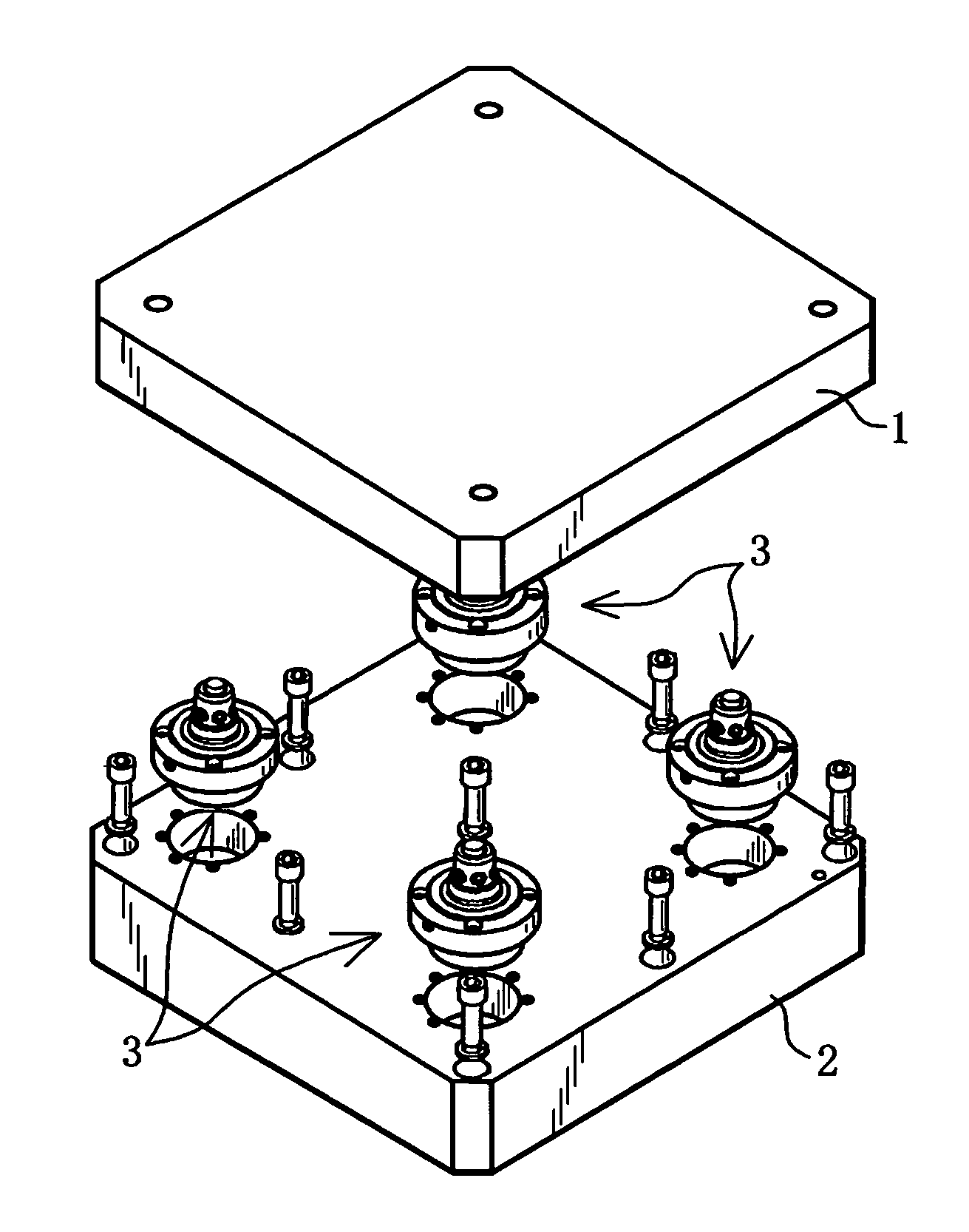
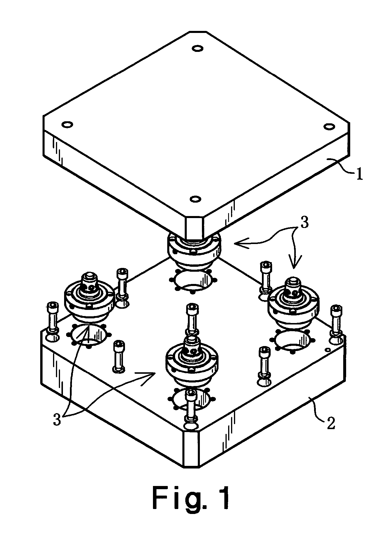
[0040]As shown in FIG. 1, the work pallet 1 which is to be fixed to the base member 2 by means of four clamp devices 3. These four clamp devices 3 position the work pallet 1 in the horizontal direction and the vertical direction, with respect to the base member 2, and fix the work pallet 1 to the base member 2.

[0041]The work pallet 1 has a thick plate shape which is approximately square in plan view, and the base member 2 also has a similar square, thick plate shape. The base member 2 may be constituted by the actual table of the machine tool. The four clamp devices 3 are disposed respectively in the four corners of the square shape of the work pallet 1 and the base membe...


PUM


Abstract

A clamp device is disclosed which maintains a stable clamped state, even if an object to be fixed, being a work pallet or die, is clamped in a repeated fashion, and which is compact in size and yet capable of clamping the object to be fixed with a large clamping force. In this clamp device (3), a plurality of partial sphere-shaped engaging recess sections (21) are formed in a bush (10), and the clamping mechanism (11) comprises a holding body (23) having a tubular holding section (23b), a plurality of steel balls (24) held movably in the radial direction in the holding section (23b) so as fact to the plurality of engaging recess sections (21), and a piston member (25) inserted movably into an axle hole (28) in the holding section (23b), whereby the plurality of steel balls (24) can be made to engage respectively with the plurality of engaging recess sections (21) by the clamp operating means (12) causing the piston member (25) to move in the axial direction thereof, and the plurality of steel balls (24) can be made to retreat from the engaging recess sections (21) by clamp releasing means (13) causing the piston member (25) to move in the axial direction thereof.

Description

TECHNICAL FIELD[0001]The present invention relates to a clamp device, and more particularly, to a clamp device capable of maintaining a stable clamped state, even when a work pallet or die is used repeatedly.BACKGROUND ART[0002]Conventionally, clamp devices of various types are used in order to fix a work pallet or die to a base member provided on a table, or the like, of a machine tool. For example, the present applicants have developed the following kind of clamp device into practical use.[0003]In this clamp device, a cylindrical holding section is formed in the upper half portion of the clamp main body, and a plurality of steel balls are held in a movable fashion in the radial direction, in this holding section. A piston member forming an output member for outputting a clamping force and a clamp releasing force is inserted movably into this holding section. This piston member is urged downwards by disc springs, for example, and when clamping is released, it is driven upwards by a...

Claims


Application Information

Patent Timeline
Patent Type & Authority Patents(United States)
IPC IPC(8): B23Q3/00B23Q1/00B23Q3/18B23Q7/14F16B2/04F16B2/16F16B21/16
CPCB23Q1/0081F16B21/165B23Q3/18
Inventor KURODA, TAKAYUKI
Owner PASCAL ENG
Why Eureka
Try Eureka