High-intensity directional light

a high-intensity, directional light technology, applied in the field of lights, can solve the problems of fluorescent lights, short life of light sources, and inability to meet the needs of users, and achieve the effects of reducing the cost of power supplies, and improving the safety of users

Inactive Publication Date: 2006-04-04
EVERBRITE
View PDF36 Cites 74 Cited by
  • Summary
  • Abstract
  • Description
  • Claims
  • Application Information

AI Technical Summary

Benefits of technology

[0010]In yet another aspect, a light-emitting apparatus adapted to project high-intensity light in a desired arc comprises a side-emitting light source having a top, a bottom, and sides connecting the top and bottom. The light source is operable to emit light through the sides to produce a cylinder of light at a desired wavelength. The apparatus also includes a base supporting the light source and an output window portion partially surrounding the light source. The window portion extends through a window arc equal to the desired arc. A multi-faceted reflector reflects light toward the window portion. The reflector and the window together define a cylinder that surrounds the sides of the light source. The facets of the multi-faceted reflector are positioned to reflect the light through the window portion to produce a wedge-shaped directional beam of light.

Problems solved by technology

Some of these light sources have relatively short lives and thus frequently failed in use or when needed, while others, such as fluorescent lights, require expensive power supplies.
In addition to short lives, some previous high-intensity light sources consumed large amounts of power to operate and generated significant heat.
Furthermore, some previous light sources required alternating current or high voltage to operate, thereby adding to the complexity of the electrical system.

Method used


Image

  • High-intensity directional light
  • High-intensity directional light
  • High-intensity directional light

Examples


Embodiment Construction

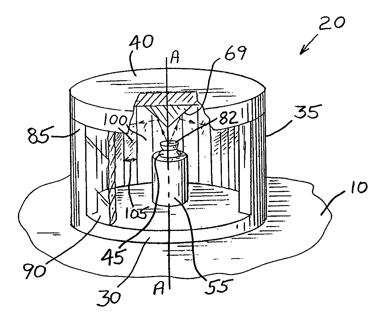
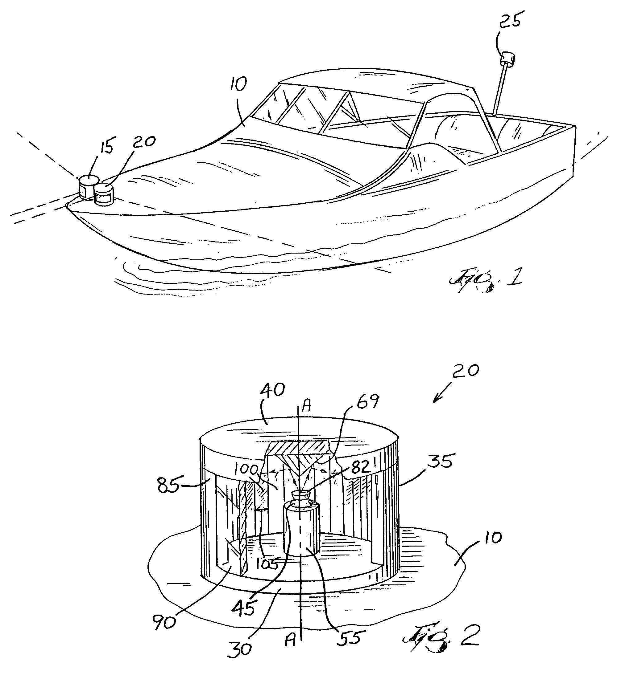
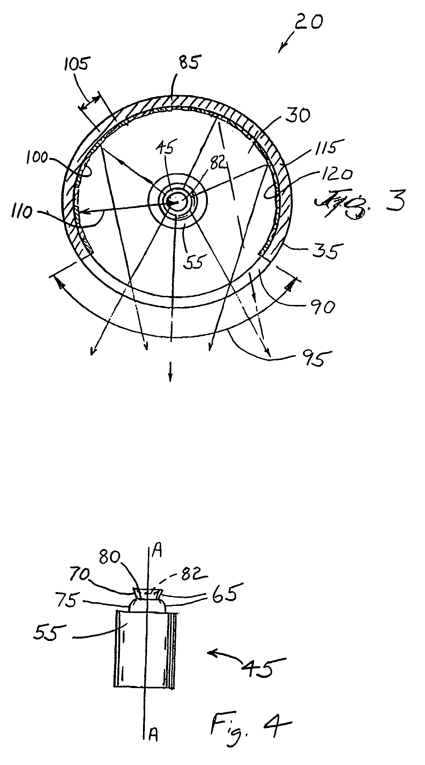
[0007]The present invention provides a high-intensity light comprising an optoelectronic device having a characteristic dimension and adapted to emit light of a desired color. The high-intensity light further comprises a base that supports the optoelectronic device and a reflector portion at least partially surrounding the optoelectronic device and spaced a distance from the optoelectronic device. The high-intensity light also includes an output window portion sized to emit light in a desired arc.

[0008]In preferred constructions, the high-intensity light includes a side emitting light emitting diode preferably surrounded by the combination of the reflector portion and the window portion. The reflector portion is spaced a distance from the diode that is approximately equal to five times the characteristic dimension. The reflector portion includes a plurality of facets, with each facet having a width at least as wide as the characteristic dimension.

[0009]In another aspect, the inventi...


PUM


Abstract

A high-intensity light comprising a side-emitting optoelectronic device adapted to emit light of a desired color. A heat sink is positioned adjacent the optoelectronic device and a reflector at least partially surrounds the optoelectronic device. The reflector is spaced a distance from the optoelectronic device. A window portion is sized to output the light in a desired arc.

Description

[0001]This application claims the benefit of prior filed co-pending provisional patent application No. 60 / 412,036 filed on Sep. 19, 2002.BACKGROUND OF THE INVENTION[0002]The present invention relates to lights, and particularly to navigational lights. More particularly the present invention relates to navigational lights that use light emitting diodes as the light source.[0003]High-intensity lights such as navigational lights are required on many types of vessels including boats, ships, and aircraft. In addition, high intensity lights are often used on buoys or other markers to aid boatman and pilots in navigation. To aid in navigation, the lights must be sufficiently bright to be seen from large distances. In addition, the lights sometimes differ in color to further aid in guiding vessels or indicating orientation of the particular craft to which the lights are attached. Furthermore, in some cases, the lights must conform to horizontal and vertical viewing angles as prescribed in v...

Claims


Application Information

Patent Timeline
Patent Type & Authority Patents(United States)
IPC IPC(8): F21V1/12B63B45/04B64D47/06F21S8/00F21V11/16F21V29/00
CPCB63B45/04B64D47/06B64C2027/8236F21Y2101/02F21V29/004F21W2101/04F21V11/16F21Y2115/10F21W2107/20F21V29/70
Inventor MOHACSI, FERENC
Owner EVERBRITE
Why Eureka
Try Eureka