
Vehicle lamp

Inactive Publication Date: 2006-04-04
KOITO MFG CO LTD
View PDF15 Cites 79 Cited by
  • Summary
  • Abstract
  • Description
  • Claims
  • Application Information

AI Technical Summary

Benefits of technology

[0017]As can be seen from the above-described configuration, a vehicle lamp of the invention is configured such that a translucent member is arranged so as to cause light originating from an LED light source oriented toward the front of a lamp to enter the translucent member and such that outgoing LED light that has entered the translucent member is reflected rearward by a front surface and then reflected forward by a rear surface, to there by exit forward of the lamp from the translucent member. An area on the front surface of the translucent member located in the vicinity of an optical axis of the LED light source is formed as a normal reflection section subjected to reflection surface treatment. An area of the front surface of the translucent member other than the normal reflection section is formed as an internal reflection section which causes the outgoing LED light having entered the translucent member to undergo internal reflection. A plurality of reflection elements are formed on the rear surface of the translucent member for subjecting the outgoing LED light reflected from the front surface of the translucent member to reflection so as to enter the internal reflection section at an incidence angle which is smaller than or equal to a critical angle. Hence, the following working-effects can be yielded.
[0023]At that time, the following working-effect can be yielded by setting the position of a boundary line between the normal reflection section and the internal reflection section to a position where the incidence angle of the light originating from the LED light source becomes equal to a substantially critical angle.

Problems solved by technology

If the geometry of the rear surface of the translucent member is set so as to enable appropriate control of reflection of the general-section-reflected light, there arises a problem of inability to appropriately control reflection of the wedged-recess-reflected light.

Method used


Image

  • Vehicle lamp
  • Vehicle lamp
  • Vehicle lamp

Examples


Embodiment Construction

[0036]Embodiments of the invention will be described herein below by reference to the accompanying drawings.

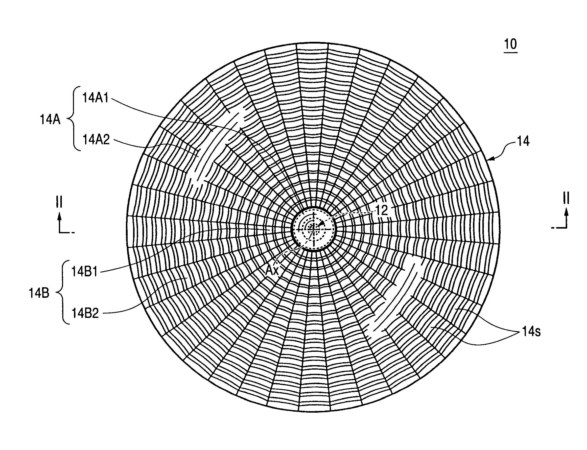
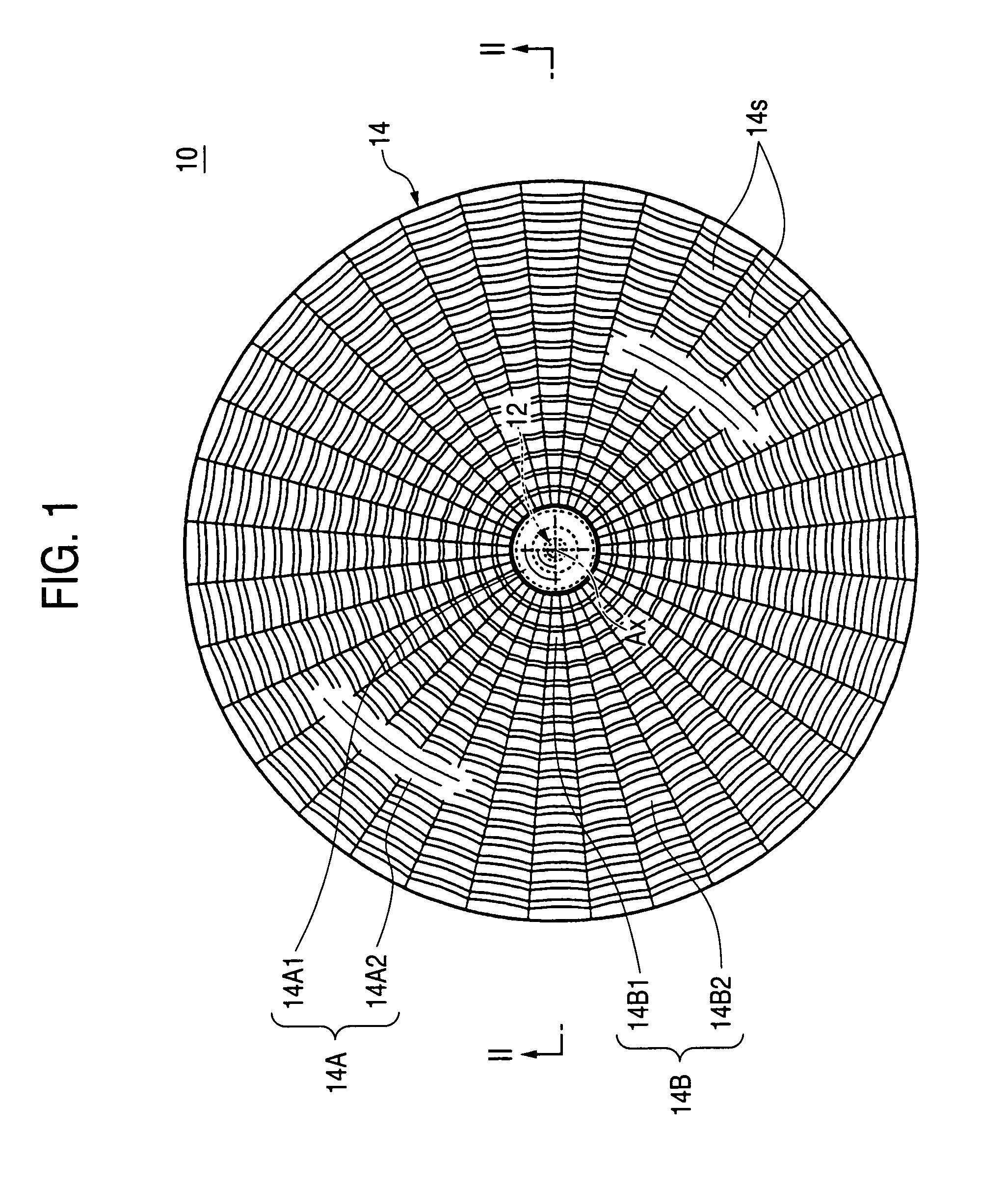
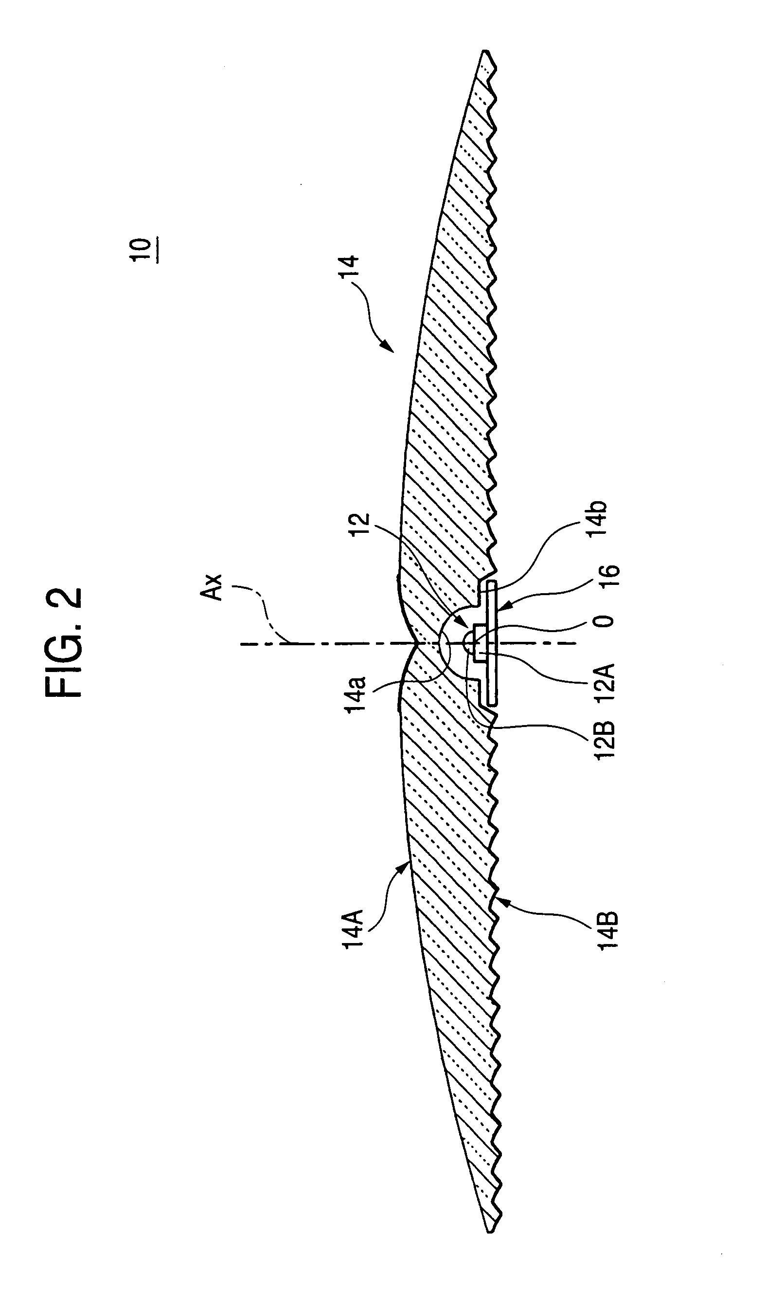
[0037]FIG. 1 is a front view showing a lamp vehicle according to an embodiment. FIG. 2 is a cross-sectional view taken along line II-II shown in FIG. 1. FIGS. 3 and 4 are detailed views of the featuring section shown in FIG. 2.

[0038]As illustrated, a vehicle lamp 10 of the embodiment is a tail lamp provided at a rear end section of the vehicle and comprises an LED light source 12 and a translucent member 14.

[0039]The LED light source 12 is oriented ahead of a lamp (i.e., a rearward direction of a vehicle (and this applies to any counterparts in the following descriptions) such that an optical axis Ax is brought into alignment with the center axis of the lamp extending in a longitudinal direction of the vehicle. The LED light source 12 is formed from an LED main body (LED chip) 12A and sealing plastic or resin 12B which covers the luminescent center O of the LED main body 12A. ...


PUM


Abstract

A translucent member is arranged so as to cause light originating from an LED light source oriented toward the front of a lamp to enter the translucent member. Outgoing LED light that has entered the translucent member is reflected rearward by a front surface, and then the light is reflected forward by a rear surface, to thereby exit forward of the lamp from the translucent member. At that time, an area on the front surface located in the vicinity of an optical axis Ax is formed as a normal reflection section subjected to reflection surface treatment. The other area of the front surface is formed as an internal reflection section which causes the outgoing LED light to undergo internal reflection. A plurality of reflection elements are formed on the rear surface of the translucent member so as to cause the outgoing LED light reflected from the front surface to enter the internal reflection section at an incidence angle which is smaller than or equal to a critical angle.

Description

BACKGROUND OF THE INVENTION[0001]1. Field of the Invention[0002]The present invention relates to a vehicle lamp equipped with an LED (light-emitting diode). More particularly, the invention relates to a vehicle lamp equipped with an LED including a normal reflection section and an internal reflection section which, when used in conjunction with a plurality of reflection elements having multiple configuration placements, are operable to control reflection and the outgoing light.[0003]2. Description of the Related Art[0004]Many vehicle lamps equipped with an LED have been recently adopted. In this regard, JP-UM-A-61-153201 describes a vehicle lamp equipped with an LED light source oriented forward of the vehicle lamp. Further, a translucent member is arranged such that light originating from the LED light source is caused to enter the translucent member. The light that has originated from the LED light source and entered the translucent member is reflected rearward by a front surface ...

Claims


Application Information

Patent Timeline
IPC IPC(8): F21V7/00F21S8/10F21V8/00F21V13/04F21W101/14F21Y101/02G02B6/00
CPCF21S48/215F21S48/2243F21S48/2268F21S48/2287F21S48/236G02B6/0038F21V7/0091G02B6/0036F21S48/24F21Y2101/02G02B6/0013F21Y2115/10F21S43/14F21S43/239F21S43/245F21S43/247F21S43/315F21S43/40F21Y2105/10F21S43/30F21W2103/00
Inventor AMANO, YASUYUKITERANISHI, YASUOKOIZUMI, HIROYA
Owner KOITO MFG CO LTD
Features
  • Generate Ideas
  • Intellectual Property
  • Life Sciences
  • Materials
  • Tech Scout
  • Unparalleled Data Quality
  • Higher Quality Content
  • 60% Fewer Hallucinations
Learn More