Internal broaching machine and internal broach

a broaching machine and internal technology, applied in the field of internal broaching machines, can solve the problems of inability to correct cutting by the broach, inability to improve the broaching accuracy of conventional construction, and adverse effect on the life of the broach, so as to achieve high broaching accuracy and improve the machining accuracy of the workpi

Active Publication Date: 2006-04-04
NACHI-FUJIKOSHI +1
View PDF17 Cites 4 Cited by
  • Summary
  • Abstract
  • Description
  • Claims
  • Application Information

AI Technical Summary

Benefits of technology

[0020]The pull head may further have a rotary direction positioning mechanism. This mechanism preferably comprises a pair of parallel flat faces formed on opposite sides of one of the ends of the broach, a pair of parallel holes radially formed in the pull head, pins slidably received in the holes respectively, and a sleeve slidably mounted on the pull head and having an inward projecting portion for engaging and pushing the pins, so that when the sleeve is moved, the projecting portion of the sleeve thrusts the pins against two ends symmetric with respect to a point of the parallel flat faces of the broach to rotate the broach from opposite directions and thereby clamp the broach with the pull head.
[0021]With the internal broaching machine

Problems solved by technology

The conventional construction thus can not be expected to improve the broaching accuracy and has an adverse effect on the life of the broach.
As described above, with the conventional machine, the broach moves

Method used


Image

  • Internal broaching machine and internal broach
  • Internal broaching machine and internal broach
  • Internal broaching machine and internal broach

Examples


Embodiment Construction

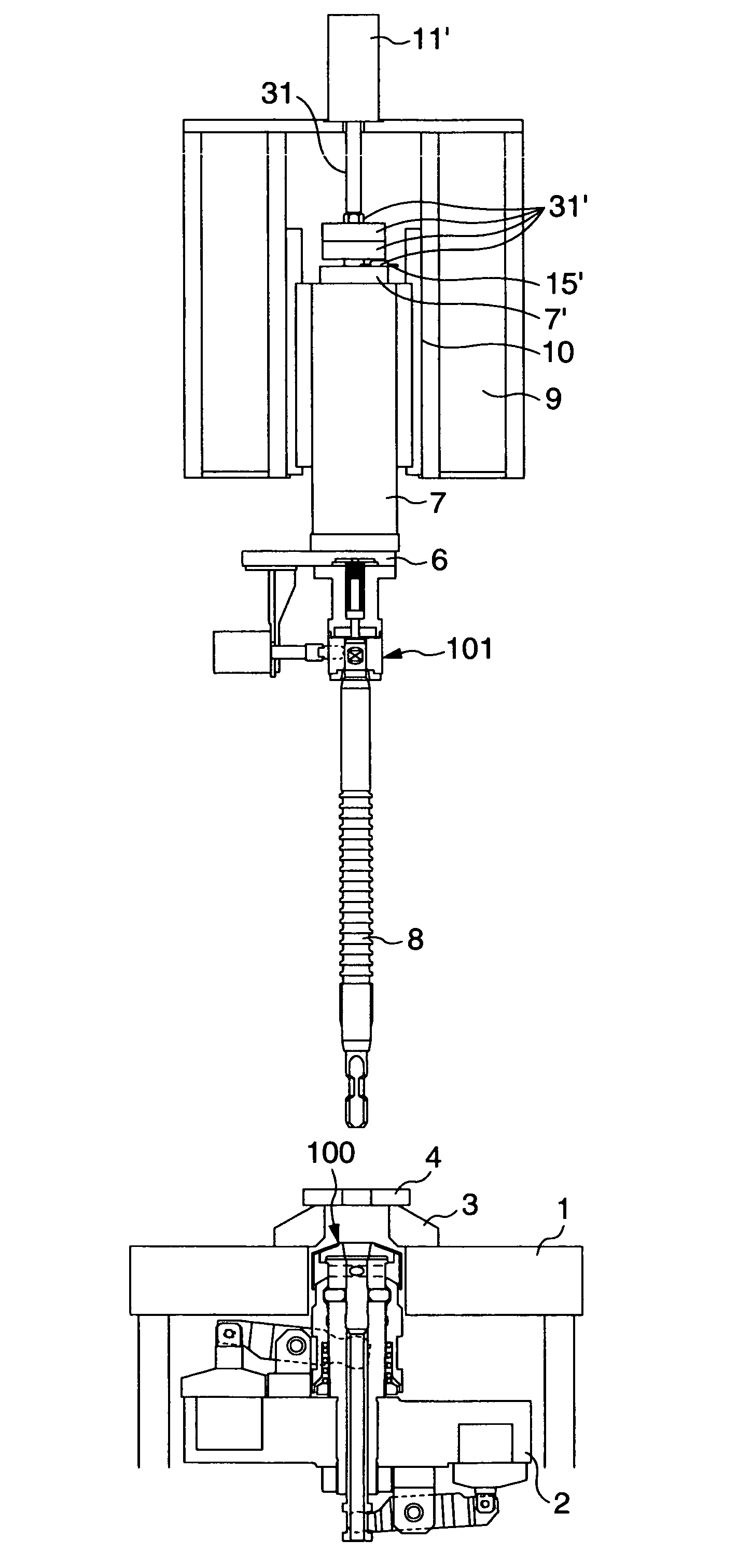
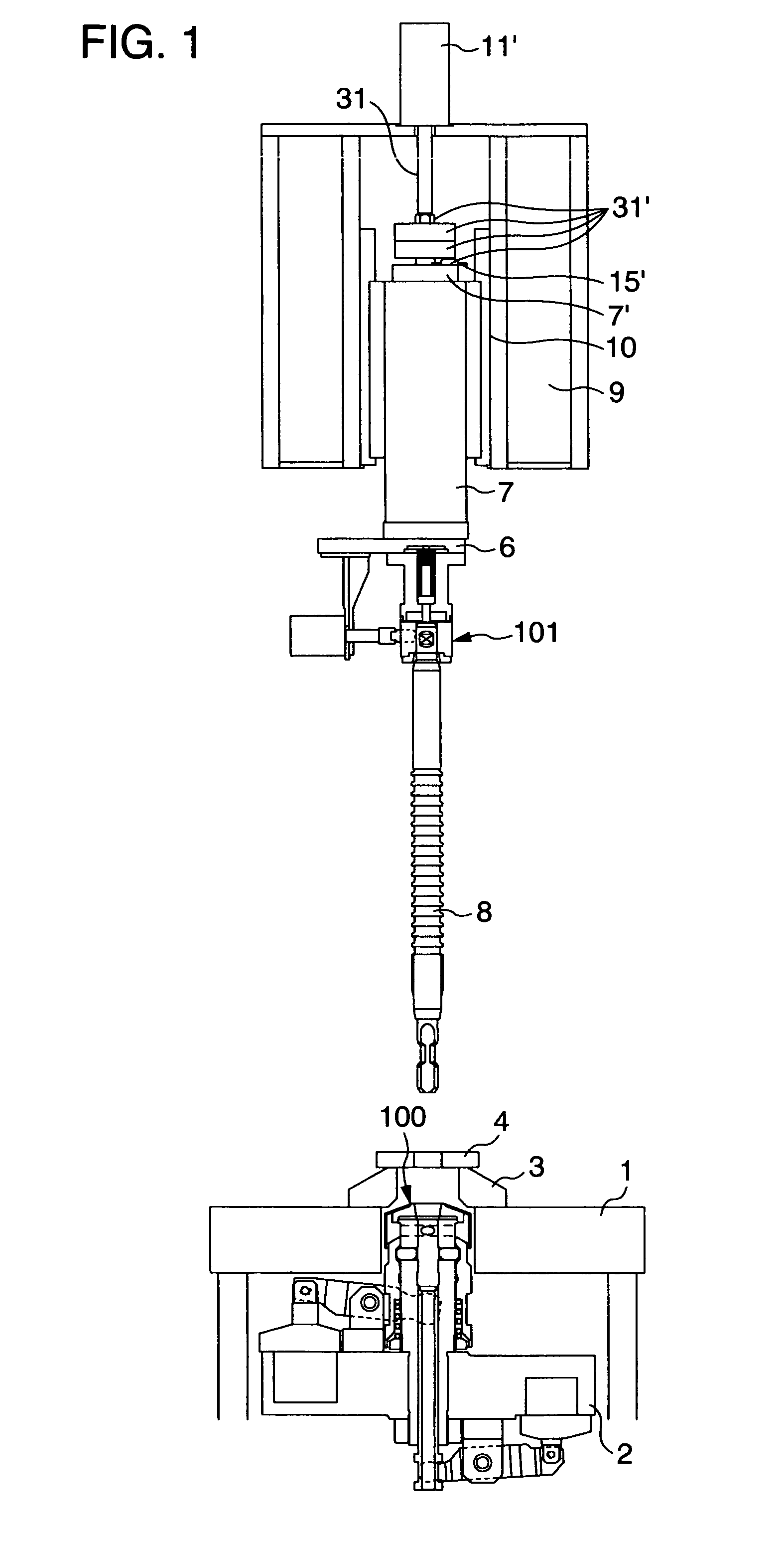
[0038]FIG. 1 illustrates an essential portion of the internal broaching machine according to an embodiment of the invention. The machine of this example is a broach-moving, work-fixed type broaching machine.

[0039]FIG. 1 shows a pull head 100 for gripping a front shank or pull end of the broach and a retrieving head 101 for gripping a rear shank or follower end of the broach. In this embodiment, the pull head 100 has a two-claw direction determination mechanism using claw members similar to those of the conventional art described above, and the retrieving head 101 is of a pin type.

[0040]The broaching machine shown in FIG. 1 is in a state that the pull head 100 is in unclamping, the retrieving head 101 is suspending the broach 8 and a workpiece 4 is placed on an upper surface of a reference jig plate 3. The reference jig plate 3 that receives the workpiece 4 is secured to a column 1 at a front of a machine body.

[0041]A slide table 2 for the pull head 100 is arranged vertically movable...


PUM


Abstract

A broach for internal broaching is formed on its pull end and/or follower end with a tapered surface machined with high accuracy. A pull head and/or a retrieving head of a broaching machine, which drivingly grip the pull end and the follower end the broach, is formed with a tapered inner surface complementary to the tapered surface of the broach. The pull head and the retrieving head grip the broach while pressing and clamping their tapered inner surface against the tapered surface, and these heads and the broach are firmly connected together. Clearances or gaps between the heads and the broach are thus eliminated, concentricity between the heads and the broach is significantly improved, and broaching can be performed with high accuracy.

Description

BACKGROUND OF THE INVENTION[0001]The present invention generally relates to an internal broaching machine. More specifically, the invention relates to an internal broaching machine which eliminates a gap between a broach and a pull head for gripping a front shank or pull end of the broach and a gap between the broach and a retrieving head for gripping a rear shank or follower end of the broach, thereby improving the accuracy of concentricity of the broach and the heads for a broaching operation.[0002]When performing an inner surface broaching using a broach, a pull head has conventionally been used for holding a pull end of the broach, such as shown in JP-A-6-126526. FIG. 13 shows such a pull head. This pull head has a body 51 formed with an insertion hole 54 for a broach pull end 50 and four claw members 52 arranged radially around an axis of the body 51. The claw members 52 can be advanced into the insertion hole 54.[0003]In operation, the broach pull end 50 is inserted into the i...

Claims


Application Information

Patent Timeline
IPC IPC(8): B23D37/10B23D43/02B23D41/04
CPCB23D37/10B23D43/02Y10T409/4077Y10T407/16Y10T409/40665
Inventor SHIMASAKU, KATSUYUKIUWAI, CHIAKI
Owner NACHI-FUJIKOSHI
Why Eureka
Try Eureka