Method for assembling gas turbine engine components

a gas turbine engine and component technology, applied in the direction of machines/engines, liquid fuel engines, forging/pressing/hammering apparatus, etc., can solve the problems of blades that demonstrate pressure ratios above or below set limits, engine failure, etc., to achieve the effect of reducing metal temperature, reducing maintenance costs, and increasing the pressure ratio across all blades

Active Publication Date: 2006-04-04
MASSACHUSETTS INST OF TECH +1
View PDF3 Cites 9 Cited by
  • Summary
  • Abstract
  • Description
  • Claims
  • Application Information

AI Technical Summary

Benefits of technology

[0007]If a turbine row is assembled exclusively from one of the classes (the low-flow blade class, for example) according to the present invention then, in accordance with the average flow characteristics of all the blades in the row, the pressure ratio across all the blades will increase. Since the lowest flowing blade in the row is subject to this increased pressure ratio, it will pass more flow than if it were assembled with a randomly drawn set of blades. Thus, if turbine blades are classified and assembled into turbine sets based on flow classes according to the invention, the lowest flowing blade passes more flow, has lower metal temperatures, and subsequently has higher life than current assembly practice would allow.

Problems solved by technology

As is well known, gas turbine engines include multiple rows of airfoils and the failure of any single airfoil in a row constitutes a failure of the engine.
There is an acceptable tolerance during manufacturing on this pressure ratio and blades that demonstrate pressure ratios above or below set limits are unacceptable.

Method used


Image

  • Method for assembling gas turbine engine components
  • Method for assembling gas turbine engine components
  • Method for assembling gas turbine engine components

Examples


Embodiment Construction

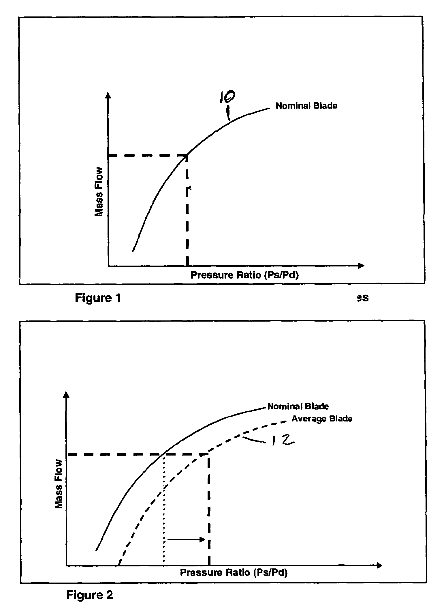
[0020]Most jet engines such as, for example, a modern high-bypass turbofan engine, have turbine cooling air delivery architectures whose mass flow is relatively insensitive to changes in pressures as compared to the turbine blades. Thus, for clarity of explanation in this specification, we will assume the turbine cooling air system behaves like a constant mass flow device. When blades are assembled into a turbine row, the blades share a common upstream supply pressure and a common downstream gaspath pressure. The supply pressure is the pressure just upstream of the entrance to the cooling passages on the bottom of the blade and the dump pressure is the gaspath pressure on the outside of the blade. If each blade in a turbine row were identically nominal (impossible in practice), then the pressure ratio across the blades during operation would be the nominal pressure ratio.

[0021]The physical features of each blade determine the relationship between the mass flow through the blade and ...


PUM

PropertyMeasurementUnit
temperature oxidation life capabilityaaaaaaaaaa
temperature creep life capabilityaaaaaaaaaa
temperature life capabilityaaaaaaaaaa

Abstract

Method for assembling into turbine sets turbine components having internal cooling passages. The turbine components are classified according to flow capability through the internal cooling passages and turbine sets are assembled in which the turbine components have the same flow capability classification.

Description

BACKGROUND OF THE INVENTION[0001]This invention relates to a method for assembling gas turbine engine components and more particularly to assembling turbine sets to increase the usable life of a row of cooled turbine airfoils.[0002]As is well known, gas turbine engines include multiple rows of airfoils and the failure of any single airfoil in a row constitutes a failure of the engine. These airfoils operate in a very harsh temperature environment and the individual airfoil temperatures are controlled by passing relatively cooler air through internal passages in the airfoil and / or applying a thin film of cool air on the external surface of the airfoil. Those skilled in the art will appreciate that the life of an individual airfoil is a function of its temperature history. In general, more cooling flow leads to lower temperatures which in turn leads to higher turbine blade or vane life. Conversely, lower life airfoils typically pass less coolant flow relative to other airfoils in a ro...

Claims


Application Information

Patent Timeline
Patent Type & Authority Patents(United States)
IPC IPC(8): F01D5/18F01D25/00F02C7/00
CPCF01D5/18F01D5/187Y10T29/4932F05D2230/61Y02T50/676Y02T50/60
Inventor SIDWELL, CARROLL V.DARMOFAL, DAVID L.
Owner MASSACHUSETTS INST OF TECH
Why Eureka
Try Eureka