Helical gear differential

a gear differential and helical gear technology, applied in the field of differentials, can solve problems such as incompatibility, and achieve the effect of limiting the axial movement of the axle sha

Active Publication Date: 2006-04-04
AMERICAN AXLE & MFG
View PDF30 Cites 52 Cited by
  • Summary
  • Abstract
  • Description
  • Claims
  • Application Information

AI Technical Summary

Problems solved by technology

However, because the access window is arranged on the outer periphery of the differential casing, there tends to be incompatibility issues with placement of the pinion pairs.

Method used


Image

  • Helical gear differential
  • Helical gear differential
  • Helical gear differential

Examples


Embodiment Construction

[0023]The following description of the preferred embodiment(s) is merely exemplary in nature and is in no way intended to limit the invention, its application, or uses. The differential assembly according to the present teachings may be utilized with a wide variety of applications and is not intended to be specifically limited to the particular application recited herein.

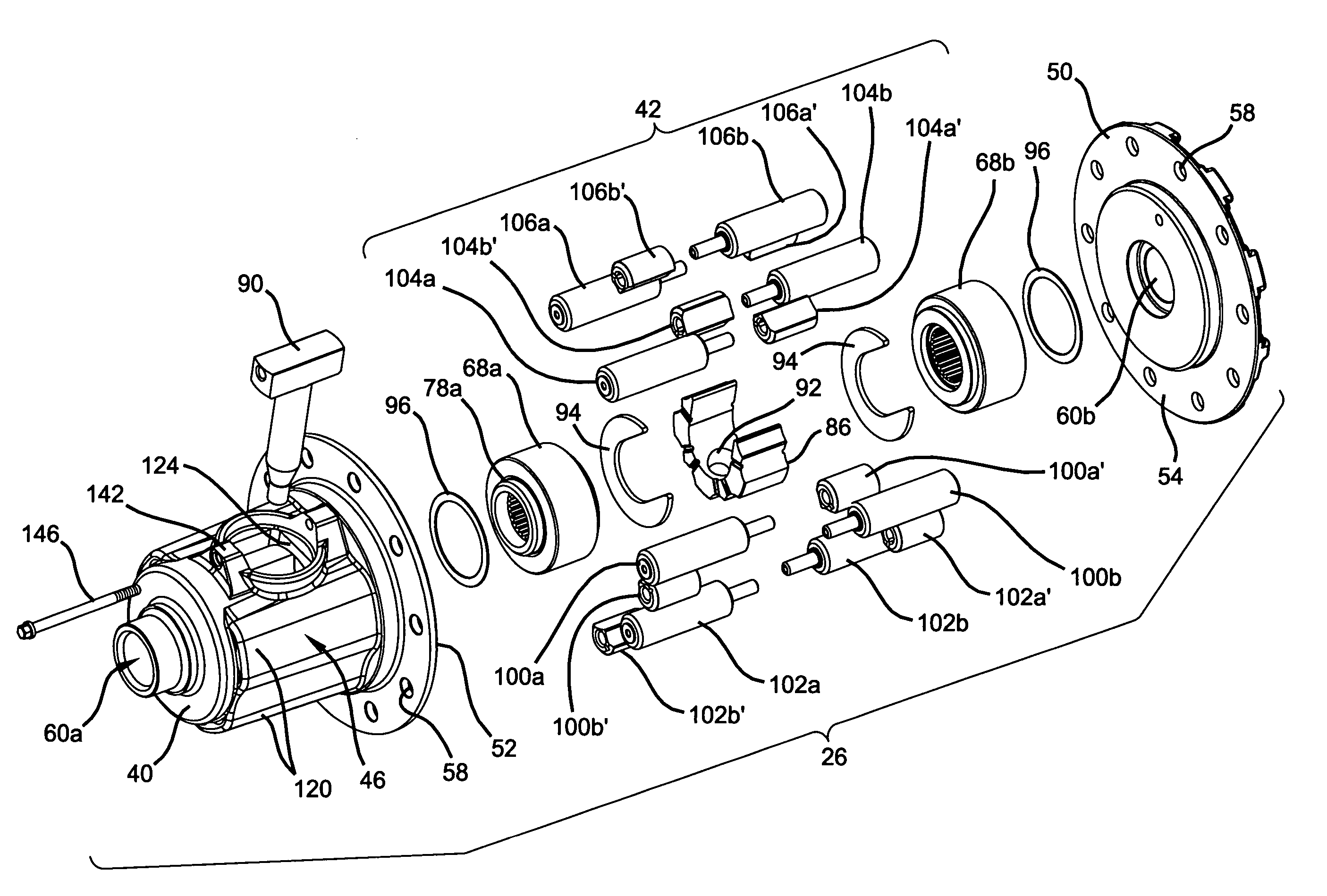
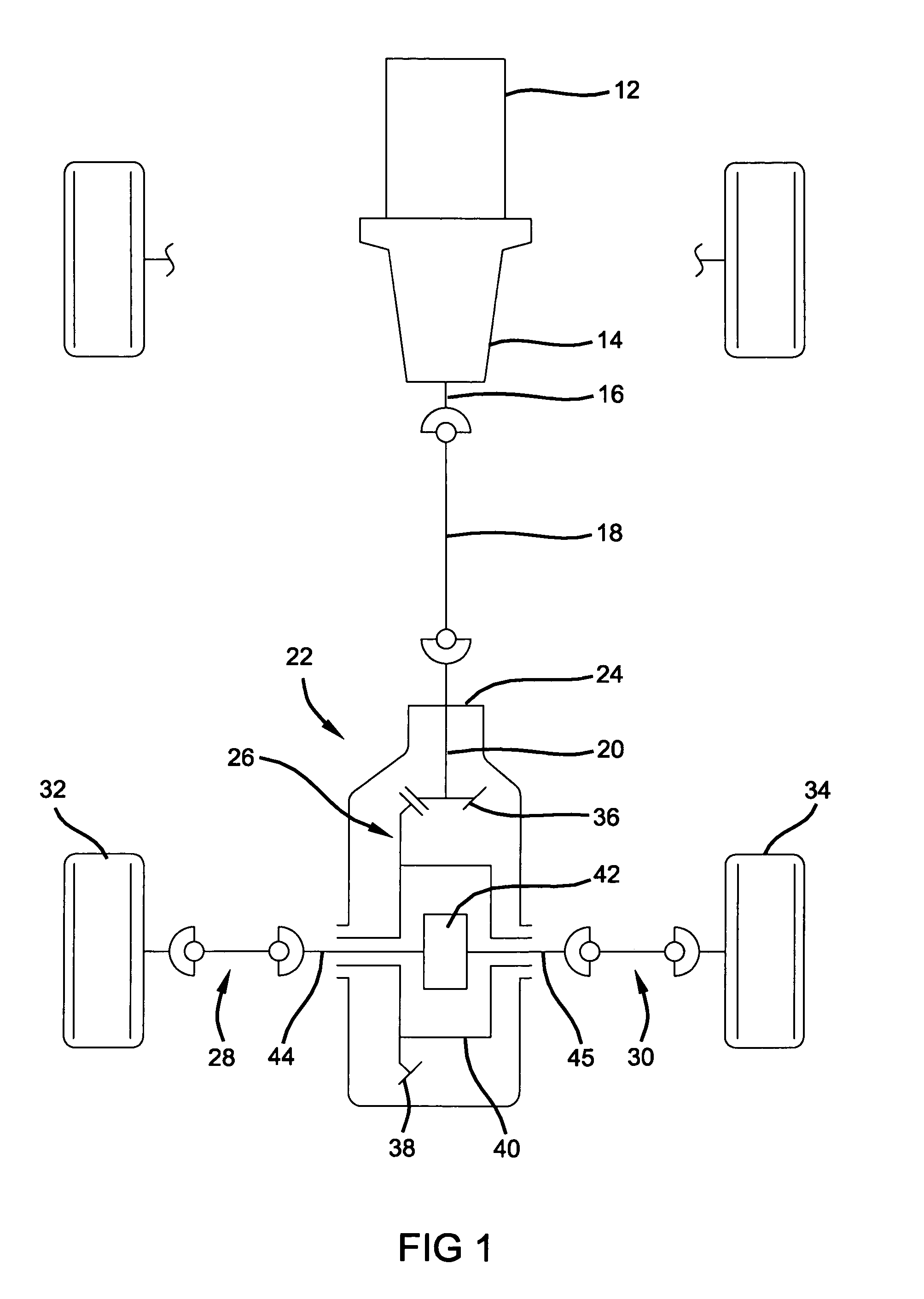
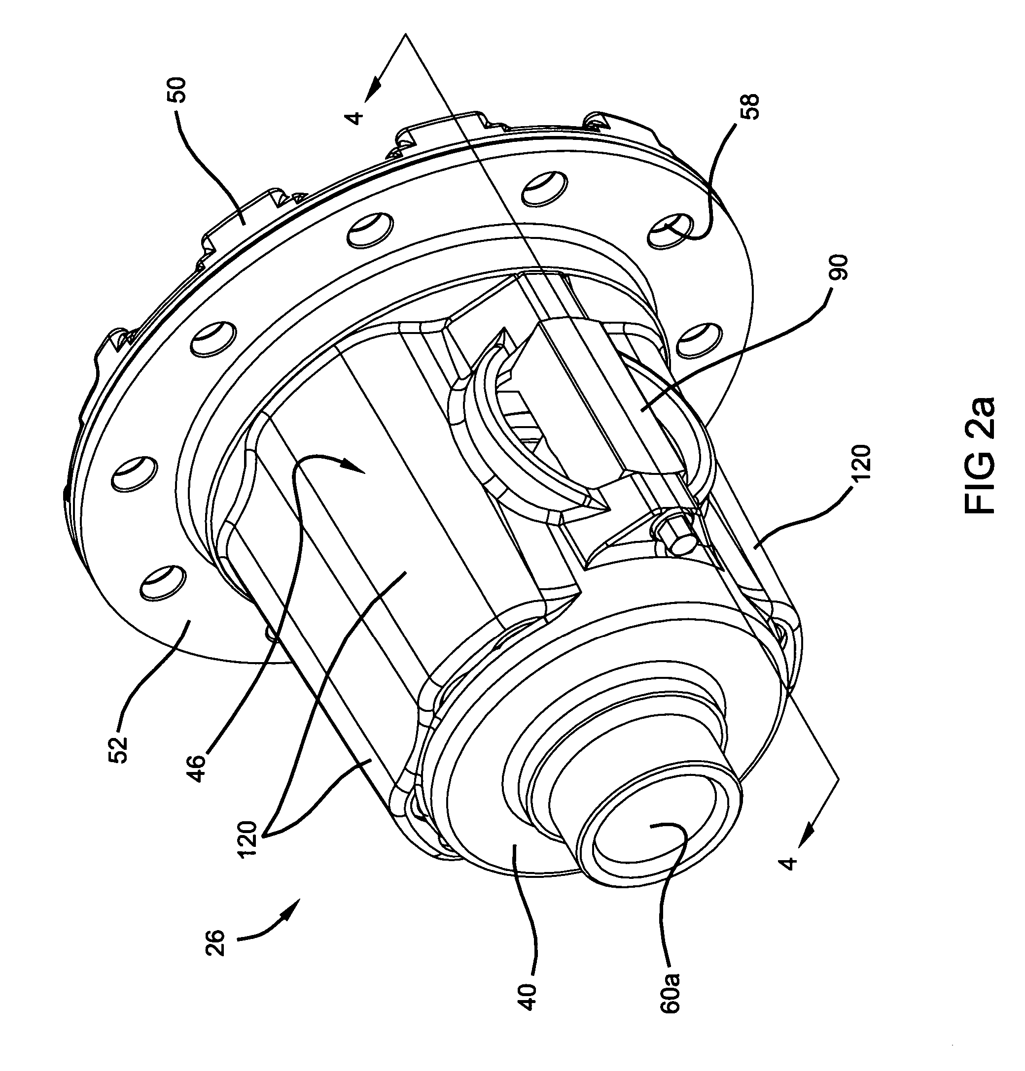
[0024]With initial reference to FIG. 1, a drivetrain 10 for an exemplary motor vehicle may include an engine 12, a transmission 14 having an output shaft 16, and a propeller shaft 18 connecting the output shaft 16 to a pinion shaft 20 of a rear axle assembly 22. The rear axle assembly 22 includes an axle housing 24, a differential assembly 26 supported in the axle housing 24, and a pair of axle shafts 28 and 30, respectively, interconnected to a left and right rear wheel 32 and 34, respectively. The pinion shaft 20 has a pinion shaft gear 36 fixed thereto which drives a ring gear 38 that may be fixed to a differenti...


PUM


Abstract

A differential assembly that includes a differential casing, which is rotatable about an axis, and a pair of side gears that are disposed within the differential casing. First, second, third and fourth pairs of pinion bores are formed in the differential casing and pairs of pinion gears are slidably and rotatably disposed in a respective pair of the pinion bores. A window opening is formed in the differential casing between the first and fourth pair of pinion gears. The second pair of pinion bores are radially offset an equivalent distance from the first and third pair of pinion bores. The differential assembly incorporates a cross pin configured to limit inward movement of a pair of axle shafts and a spacer that limits inward movement of the side gears.

Description

FIELD OF THE INVENTION[0001]The present invention relates to differentials for use in automotive drivelines and, more particularly, to a pinion pair arrangement for a four pinion pair, C-clip differential having independent control of side gear endplay and axle shaft endplay.BACKGROUND OF THE INVENTION[0002]Differentials of the type used in automotive drivelines generally include a planetary gearset supported within a differential casing to facilitate relative rotation (i.e., speed differentiation) between a pair of output shafts. The planetary gearset typically includes helical side gears fixed to the end of the output shafts, which are meshed with paired sets of helical pinion gears. This type of differentiation is known as a parallel axis helical gear differential. In response to input torque applied to the differential case, the torque transmitted through meshed engagement of the side gears and pinion gears generates thrust forces. To accommodate these and other operating forces...

Claims


Application Information

Patent Timeline
Patent Type & Authority Patents(United States)
IPC IPC(8): F16H48/06F16H48/20
CPCF16H48/10F16H48/11Y10T74/2186Y10T74/2188F16H2048/106B60K17/16
Inventor VALENTE, PAUL J.
Owner AMERICAN AXLE & MFG
Why Eureka
Try Eureka