

Cross training exercise apparatus
- Summary
- Abstract
- Description
- Claims
- Application Information
AI Technical Summary
Benefits of technology
Problems solved by technology
Method used
Image

Examples
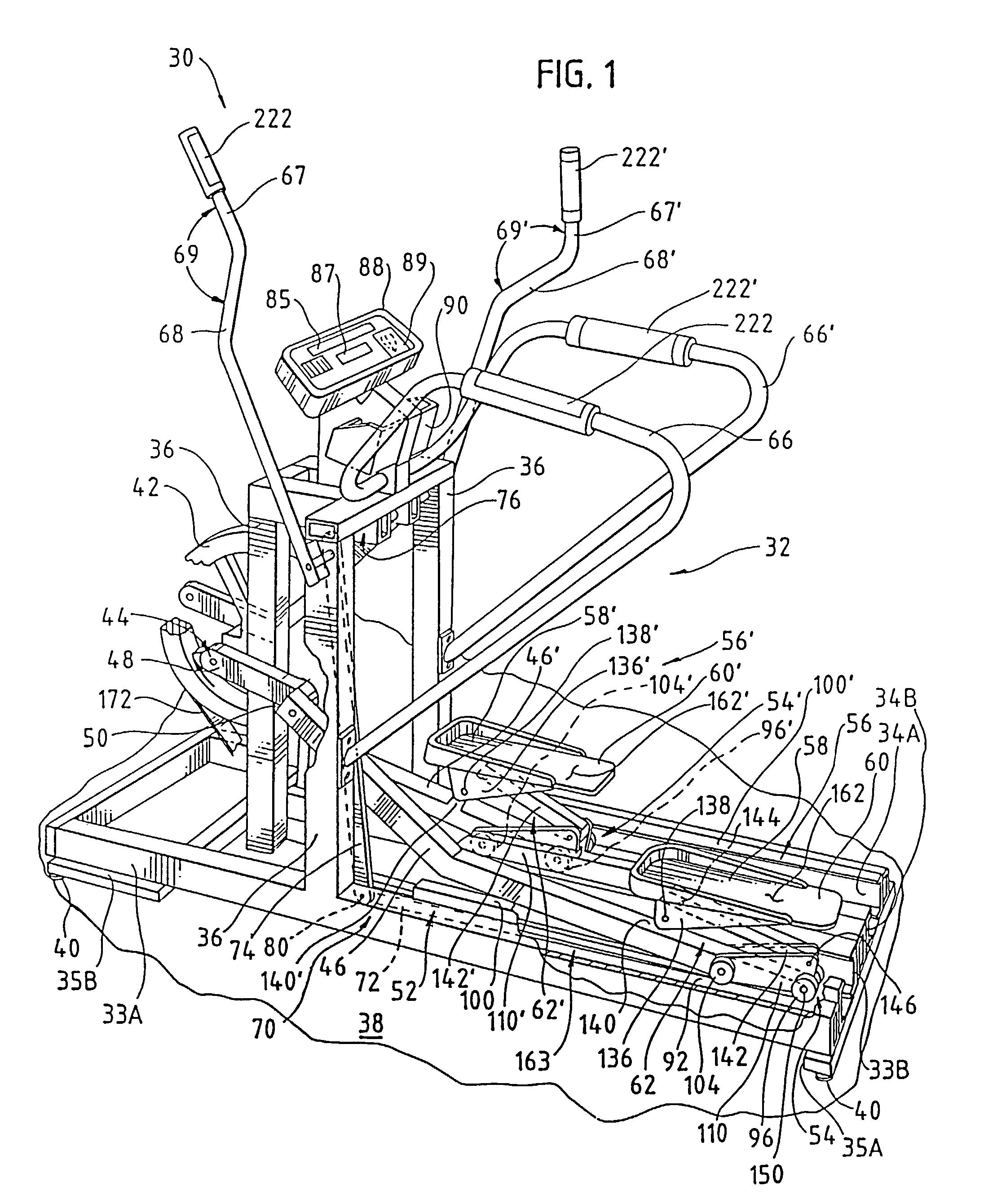
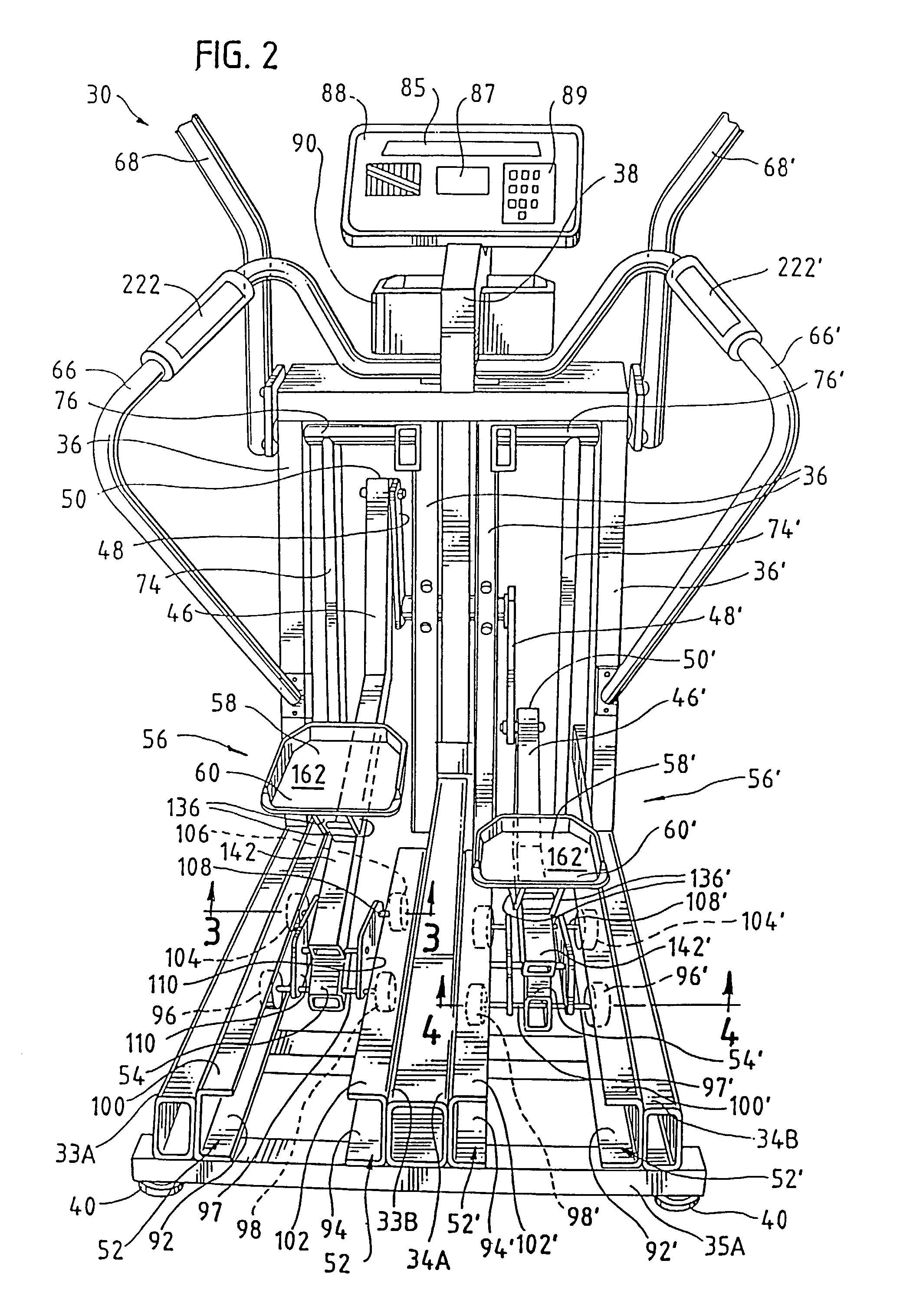
embodiment 30
[0111]The movement of the pedal 56, which is determined by the components of the pedal actuation assembly 272, is now discussed in detail with reference to FIGS. 22A–22H and 23. FIGS. 22A–22H trace the motion of the pedal 56 as the pedal 56 completes one forward-stepping revolution along the elliptical path 320, beginning at the rearmost position on the reciprocating linear path 318 of the second end 314 of the pedal tie 282. As with the previous embodiment 30, the apparatus 270 can be operated both in a forward-stepping mode and in a backward-stepping mode. When the apparatus 270 is operated in the forward-stepping mode, the pedal 56 travels in the counter-clockwise sequence illustrated in FIGS. 22A–22H. Alternatively, when the apparatus 270 is operated in the backward-stepping mode, the sequence of the pedal 56 is reversed so that the pedal moves from the starting point, shown in FIG. 22A, in a clockwise direction to the position shown in FIG. 22H.
[0112]Beginning at FIG. 22A, the ...
embodiment 270
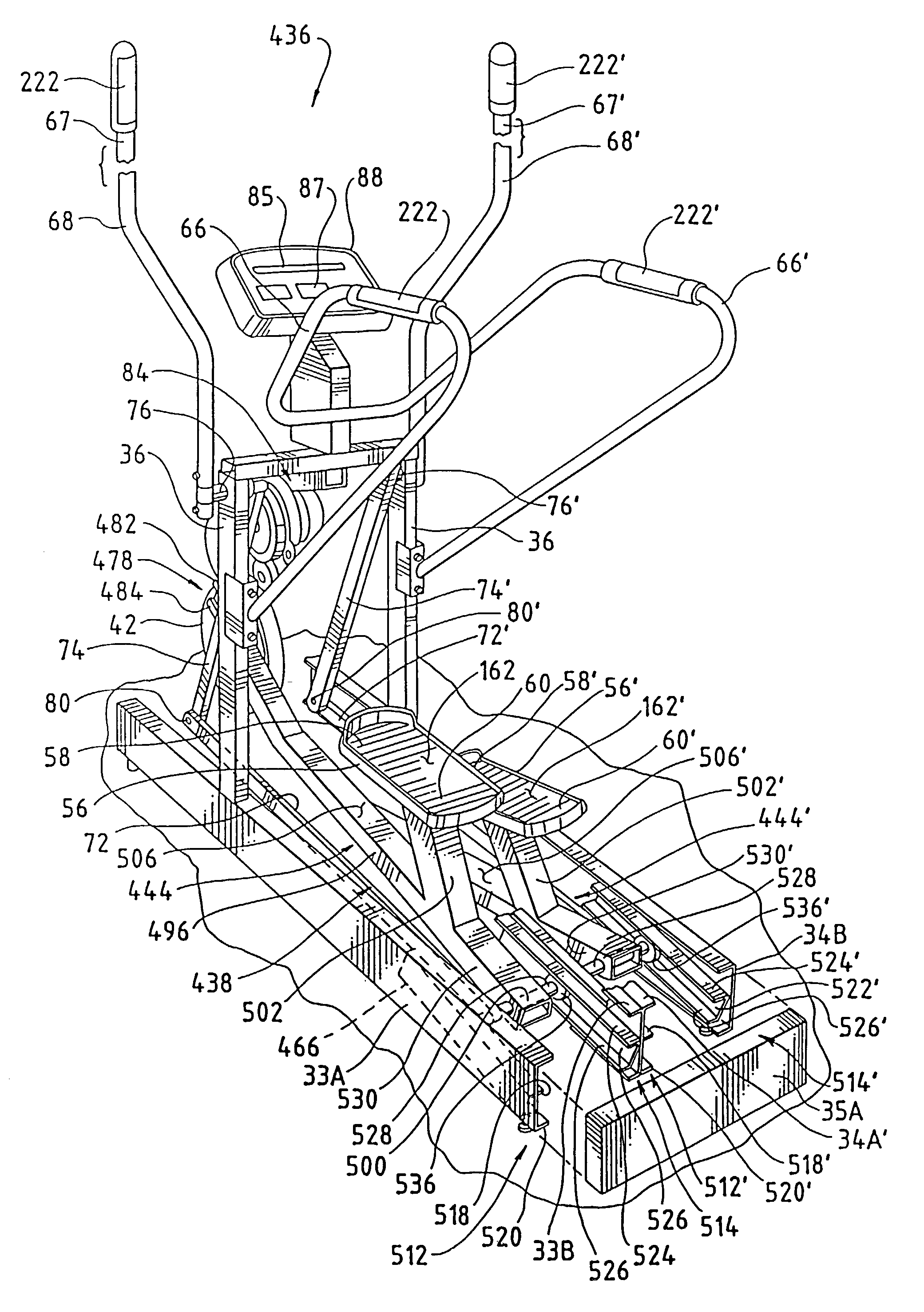
[0126]FIG. 30 shows the preferred embodiment of the offset coupling assembly 440 of the elliptical generator 442 which, like the offset coupling assembly 274 of the previous embodiment 270 of the invention, includes two crank arms 448 and 450, two axles 454 and 456, and a roller 458. A first end 460 of the first crank arm 448 is secured to the pulley pivot axis 44. The first axle 454 is secured to the first crank arm 448 proximate a second end 462 thereof and is substantially perpendicular to the first crank arm 448. As the pulley 42 rotates, the first axle 454 traces a first generally circular path 468 (shown in FIGS. 33A–33H). A first end 470 of the second crank arm 450 is secured to the first axle 454. The second axle 456 is secured to the second crank arm 450 proximate a second end 472 thereof and is substantially perpendicular to the second crank arm 450. The second axle 456 traces a second generally circular path 474 (shown in FIGS. 33A–33H) as the pulley 42 rotates. In the pr...
second embodiment
[0141]FIG. 35 shows a pedal bar 554 that can be used in the pedal actuation assembly 438 of the apparatus 436. As with the previous embodiment 444, the pedal bar 554 transmits the elliptical motion generated proximate the pivot axis 44 to the pedal 56. The pedal bar 554 differs from the previous embodiment 444 in its shape. The pedal bar 554 includes a first elongated member 556 which has a first end 558 that is rigidly secured to the portion 499 of the ellipse generator 442. A second end 560 of the elongated member 554 is rigidly secured to a second elongated member 562 at a first end 564 thereof. The axle 528 extends through a second end 566 of the second elongated member 562. The rollers 534 and 536 are pivotally coupled to the axle 528 as previously described. The second end 566 of the second elongated member 562 thus rolling engages the track 446. The first end 558 of the first elongated member 556 forms the first end of the pedal bar 554 and the second end 566 of the second el...
PUM
 Abstract
Description
Claims
Application Information