
Device for connecting a longitudinal bar to a pedicle screw

a technology of longitudinal bars and screws, applied in the field of devices for connecting longitudinal bars to pedicles, can solve the problems of relative complexity of locking mechanisms for securing longitudinal bars, and achieve the effect of convenient handling

Inactive Publication Date: 2006-04-04
SYNTHES USA
View PDF50 Cites 343 Cited by
  • Summary
  • Abstract
  • Description
  • Claims
  • Application Information

AI Technical Summary

Benefits of technology

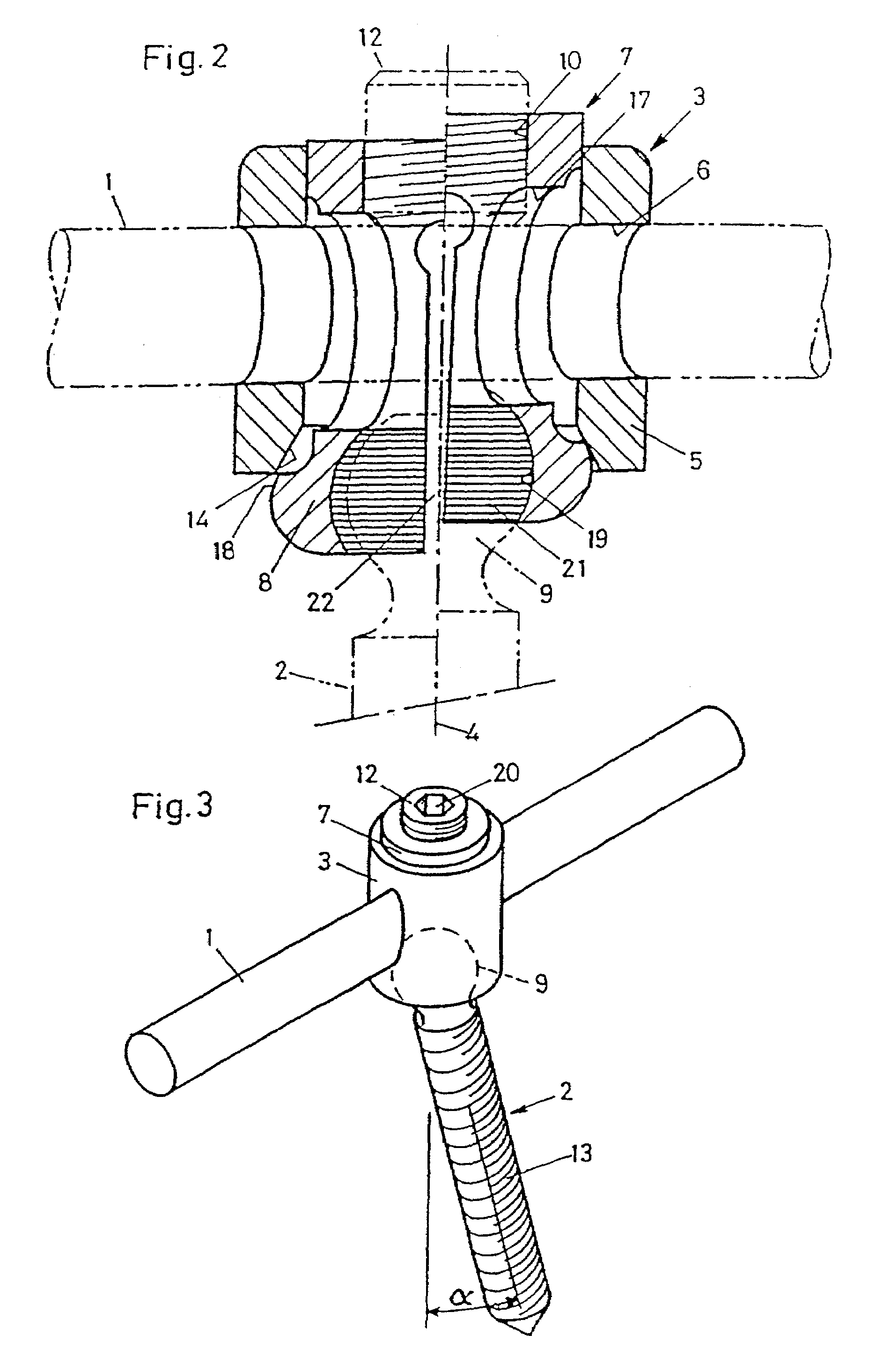
[0009]Thus, in comparison with known devices, the device according to this invention offers the advantage that the pedicle screws can not only be secured exactly perpendicular to the longitudinal bar but also permit an angle bend of up to ±25°. This is especially important if the longitudinal bar has not been bent accurately, which leads to major problems in assembly with traditional systems.

Problems solved by technology

The disadvantage of this and similar pedicle screws is the relatively complicated locking mechanisms for securing the longitudinal bar inserted into the open pedicle screw head.
Furthermore, in most cases the head of the screw can be aligned with the position of the longitudinal bar only to a limited extent, necessitating complicated bending of the longitudinal bar to correct the angle.

Method used


Image

  • Device for connecting a longitudinal bar to a pedicle screw
  • Device for connecting a longitudinal bar to a pedicle screw
  • Device for connecting a longitudinal bar to a pedicle screw

Examples


Embodiment Construction

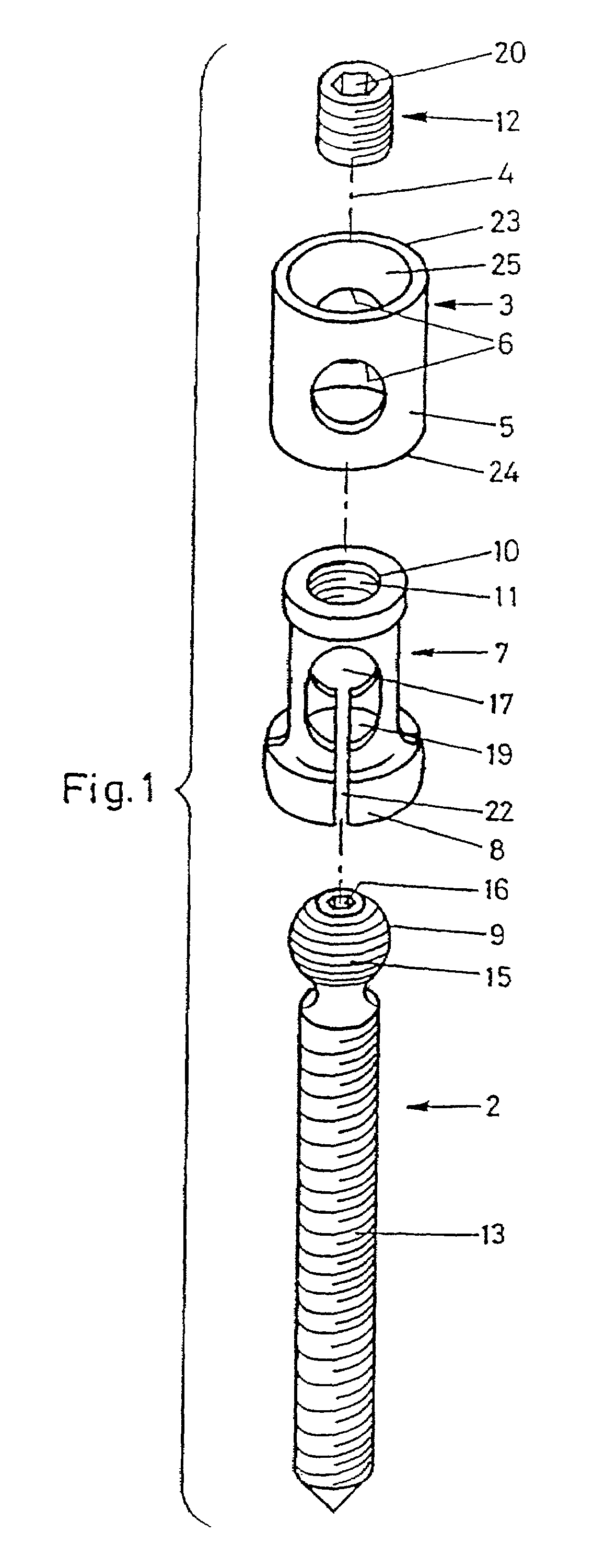
[0026]The device according to this invention illustrated in FIGS. 1 and 2 consists essentially of a body 3 in the form of a hollow cylindrical bushing with an axis 4 (axis of the hollow cylinder) and a hollow cylindrical collet chuck 7 arranged coaxially so it can slide in the interior of the body 3.

[0027]The body 3 has a through hole 6 running across the axis 4—intersecting the cylindrical surface of the hollow cylinder at two points symmetrically with the axis 4—and the collet chuck 7 has a through hole 17 running across the axis 4. Insertion of a longitudinal bar 1 running across the axis 4 is made possibly by the aligned arrangement of the through holes 6 and 17 as illustrated in FIG. 2.

[0028]In its upper part, the collet chuck 7 is secured within the (hollow cylindrical) body 3 by a press fit and can be displaced axially with respect to the body 3 when the relatively high force of the press fit is overcome.

[0029]The (hollow cylindrical) body 3 and the collet chuck 7 are prefera...


PUM


Abstract

The invention is directed to a device for connecting a longitudinal bar to a pedicle screw for fixation of the spine. The device includes a body having an axis, an upper end, a lower end, a hole coaxial with the axis, and a through hole positioned perpendicular to the axis. The device also includes a coller chuck slidably disposed within the hole. The coller chuck includes a through hole substantially aligned with the through hole of the body for receiving the longitudinal bar, and a chamber defined by elastic tongues for receiving the head of the pedicle screw.

Description

CROSS REFERENCE TO RELATED APPLICATIONS[0001]This is a continuation of U.S. patent application Ser. No. 09 / 341,963, now U.S. Pat. No. 6,371,957, filed Jul. 21, 1999, which is a continuation of PCT International Application No. PCT / CH97 / 00019, filed Jan. 22, 1997.FIELD OF THE INVENTION[0002]This invention concerns a device for connecting a longitudinal bar to a pedicle screw.BACKGROUND OF THE INVENTION[0003]From the related art, a large number of pedicle screws for fixation of the spinal column are already known; these known pedicle screws have the advantage that the individual pedicle screw can be attached to or removed from the longitudinal bar at any time without having to dismantle the entire fixation system. Such a pedicle screw is known from European Patent No. 330, 881 B, for example.[0004]The disadvantage of this and similar pedicle screws is the relatively complicated locking mechanisms for securing the longitudinal bar inserted into the open pedicle screw head. Furthermore,...

Claims


Application Information

Patent Timeline
IPC IPC(8): A61B17/70A61B17/58
CPCA61B17/7032A61B17/7035A61B17/7037A61B17/7034
Inventor AMREIN, THOMASHESS, MARTIN
Owner SYNTHES USA
Learn More