Method of manufacturing inner blade for electric razor

a technology of inner cutter and dry shaver, which is applied in the direction of manufacturing tools, furnaces, heat treatment equipment, etc., can solve the problems of reducing the cutting efficiency of the whole inner cutter, wasting material, and limited number of blades per unit length of metal plates, so as to reduce waste of material, reduce waste, and increase yield

Inactive Publication Date: 2006-04-04
MATSUSHITA ELECTRIC WORKS LTD
View PDF15 Cites 27 Cited by
  • Summary
  • Abstract
  • Description
  • Claims
  • Application Information

AI Technical Summary

Benefits of technology

[0003]In view of the above insufficiency, the present invention has been accomplished to provide a unique method of fabricating an inner cutter for a dry shaver. The method in accordance with the present invention utilizes a flat metal plate from which a plurality of parallel blades are formed. Firstly, the metal plate is processed to form a plurality of parallel straight slits therein to leave an array of straight beams each defined between the adjacent ones of the straight slits, and to leave a frame around the array. Then, the beams are forged and ground at a portion or segment of each beam to give cutting edges extending along each one of the segments. After or before giving the cutting edges, the metal plate is bent into a generally U-shaped configuration so as to correspondingly curve the beams and shape the beams into the blades having the arcuate contour and the cutting edges. The frame is formed with a joint for connection with a driving source of moving the inner cutter relative t

Problems solved by technology

Notwithstanding that the blades are only required to have a thickness corresponding to the thickness of the metal plate, each blade occupy a relatively large area or dimension along the length of the metal plate before being bent upright so that the number of the blades per unit length of the metal plate is limited, resulting in waste of material.

Method used


Image

  • Method of manufacturing inner blade for electric razor
  • Method of manufacturing inner blade for electric razor
  • Method of manufacturing inner blade for electric razor

Examples


Embodiment Construction

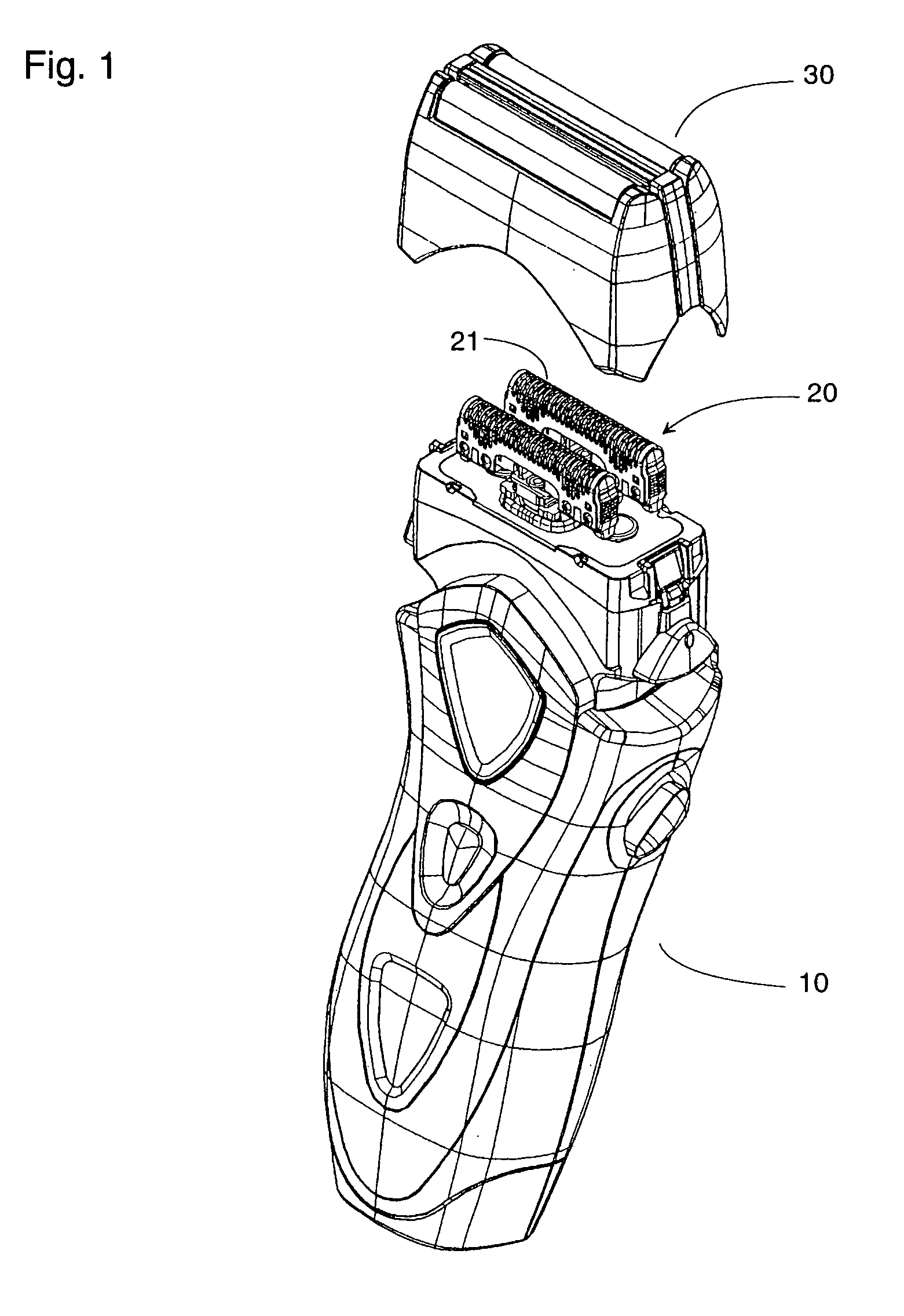
[0035]Referring now to FIGS. 1 to 3, there is shown a dry shaver with an inner cutter 20 which is fabricated in accordance with the present invention. The inner cutter 20 has a plurality of parallel blades 21 for shearing engagement with a complementary outer cutter or foil 30 having a number of perforations responsible for introducing hairs. The inner cutter 20 is connected to a driving source incorporated in a shaver housing 10 and is driven thereby to oscillate relative to the outer cutter 30 for shearing the hairs.

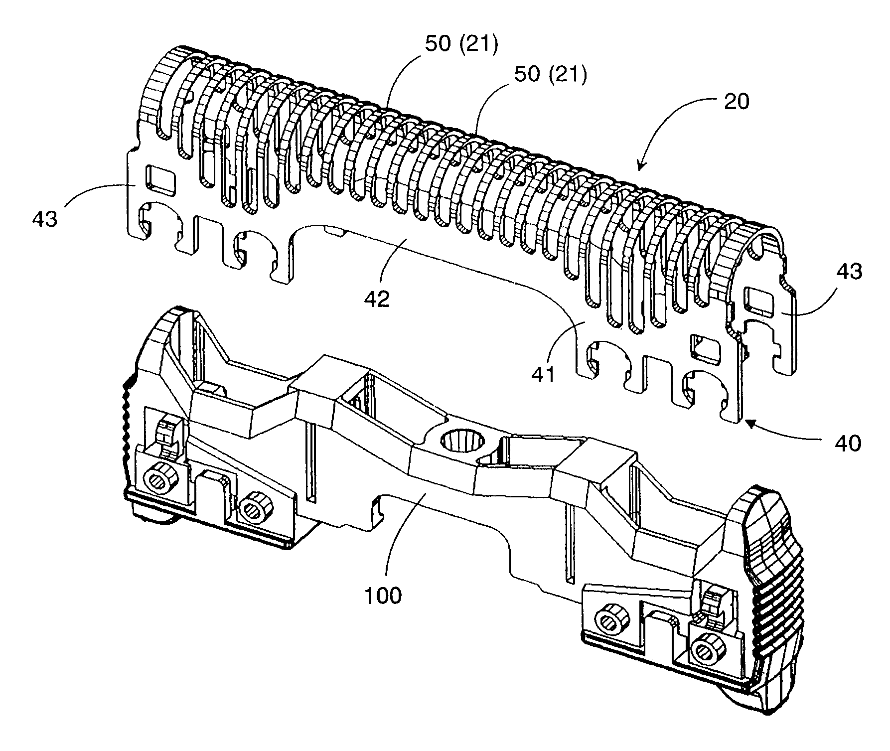
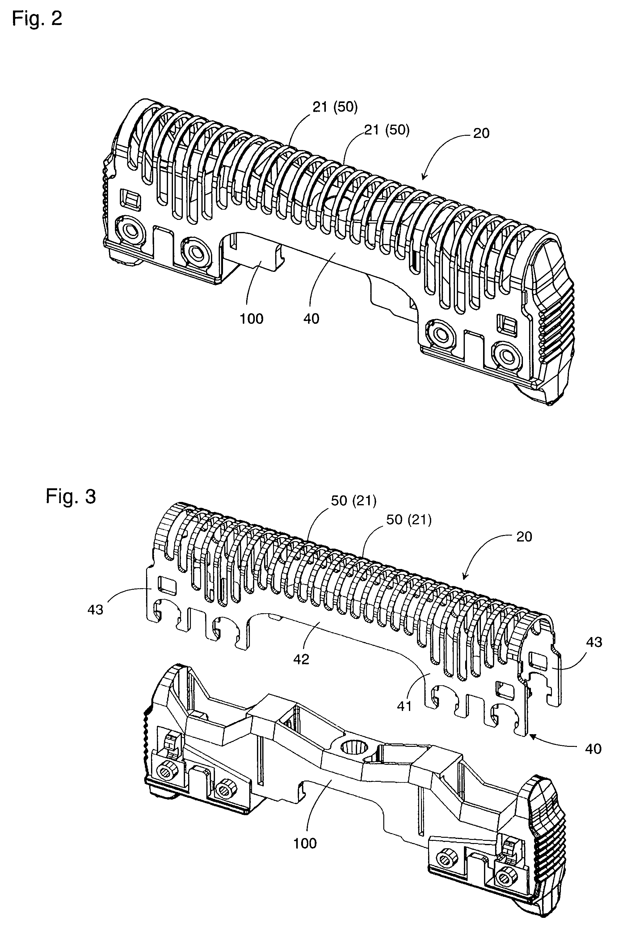
[0036]As shown in FIGS. 2 and 3, the inner cutter 20 is formed from a single metal plate 40 to have a plurality of generally U-shaped blades 21 which are parallel to each other and are supported by a common frame 41. The frame 41 is secured to a joint 100 which is molded from a plastic material for connection with the driving source. The metal plate 40 is made from a martensite stainless steel into a generally rectangular configuration having a thickness of at least 0....


PUM

PropertyMeasurementUnit
Thicknessaaaaaaaaaa
Lengthaaaaaaaaaa
Angleaaaaaaaaaa

Abstract

An inner cutter for a dry shaver is fabricated from a metal plate to have a plurality of blades each provided with cutting edges. The metal plate includes a plurality of parallel straight slits to leave an array of straight beams each defined between the adjacent ones of the slits. The beams are forged and ground at a segment of each beam to give the cutting edges thereto. After making the cutting edges, the metal plate is bent into a generally U-shaped configuration so as to correspondingly curve the beams and shape the beams into the blades having the arcuate contour and the cutting edges. The metal plate is provided with a joint for connection with a driving source of moving the inner cutter relative to an outer cutter.

Description

TECHNICAL FIELD[0001]The present invention is directed to a method of fabricating an inner cutter for a dry shaver, and more particular to the inner cutter having a plurality of parallel blades of generally U-shaped configuration supported on a frame.BACKGROUND ART[0002]U.S. Pat. No. 5,214,833 discloses a prior inner cutter for a dry shaver. The inner cutter is punched from a single metal plate to have a plurality of blades for shearing contact with a complementary outer cutter. The blades are bent upright from the metal plate to have arcuate contours with cutting edges. For this purpose, the metal plate is firstly processed to have a plurality of arcuate slits arranged along a length of the metal plate to define, between the adjacent slits, arcuate beams which are to be later bent upward to form the blades. Notwithstanding that the blades are only required to have a thickness corresponding to the thickness of the metal plate, each blade occupy a relatively large area or dimension a...

Claims


Application Information

Patent Timeline
IPC IPC(8): B26B19/06B26B19/04
CPCB26B19/044Y10T29/49996B26B19/04
Inventor OTANI, RYUJIIKUTA, TOSHIOKOZAI, TAKASHIOKADA, HIROYUKIFUJIMOTO, SHINJISAKON, SHIGETOSHI
Owner MATSUSHITA ELECTRIC WORKS LTD
Why Eureka
Try Eureka