Push-on switch

a push-on switch and switch technology, applied in the direction of contact electric connection, snap-action arrangement, contacts, etc., can solve the problem of difficult to simplify control, and achieve the effect of improving the reliability of the connecting part to the printed wiring board and simplifying the quality control of the connecting sta

Active Publication Date: 2006-04-04
PANASONIC CORP
View PDF11 Cites 82 Cited by
  • Summary
  • Abstract
  • Description
  • Claims
  • Application Information

AI Technical Summary

Benefits of technology

[0027]a maintaining means that is disposed on the front side of the pushing direction of the operation body and fixes the switch to the printed wiring board. The push-on switch, thanks to the maintaining means, is stably mounted to the printed wiring board also when a pushing operation is repeated. Especially, the maintaining means is disposed on the front side of the pushing direction by the printed wiring board, so that reliability of the connecting part to the printed wiring board is improved and the quality control of the connecting state can be simplified even when the operating direction is inclined slightly vertically.

Problems solved by technology

The control is difficult to be simplified.

Method used


Image

  • Push-on switch
  • Push-on switch
  • Push-on switch

Examples


exemplary embodiments

[0040](Exemplary Embodiments)

[0041]A push-on switch of the present invention will be specifically described in accordance with exemplary embodiments.

[0042]Elements similar to those described in the conventional art are denoted with the same reference numbers, and the descriptions of those elements are omitted.

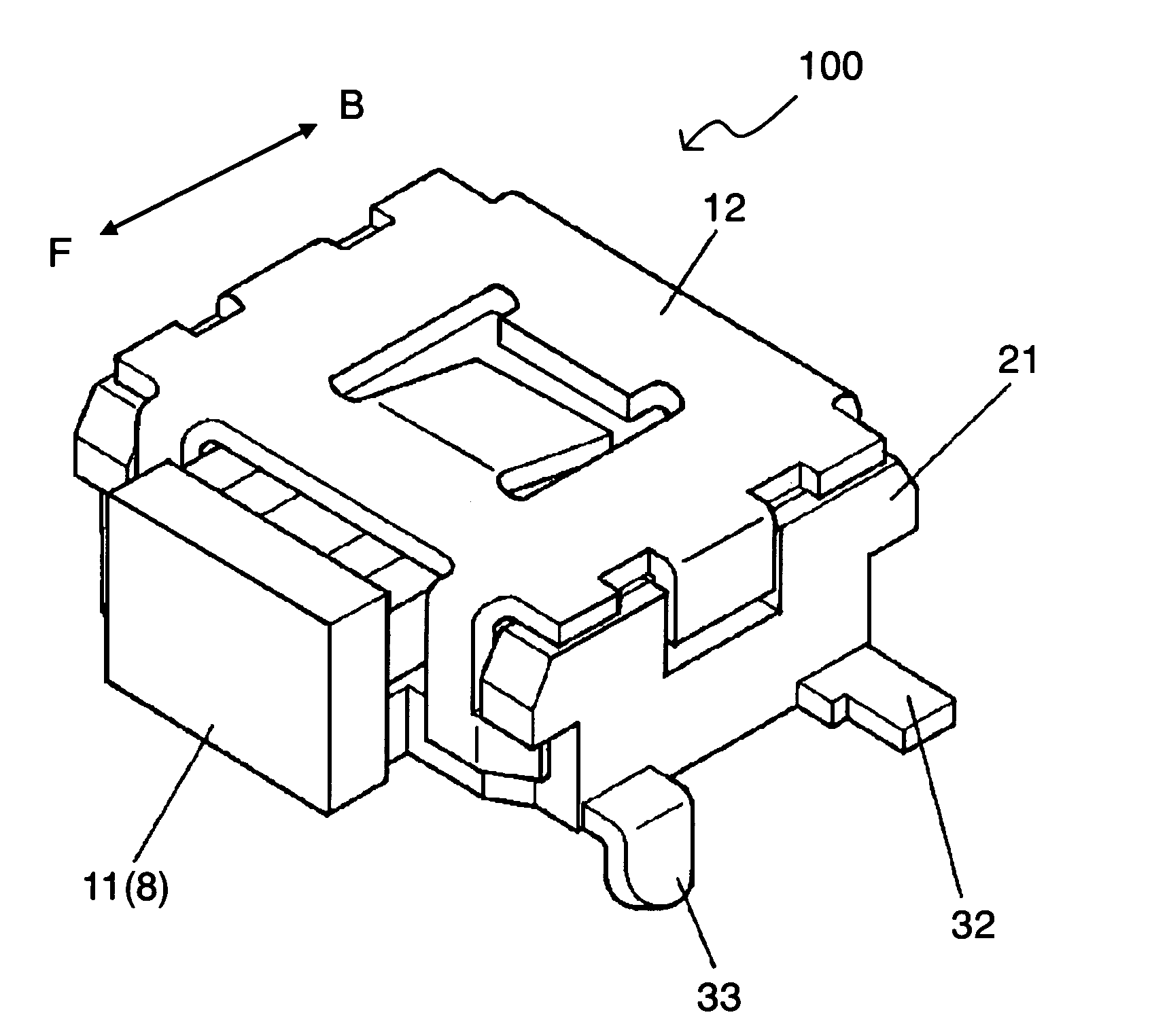
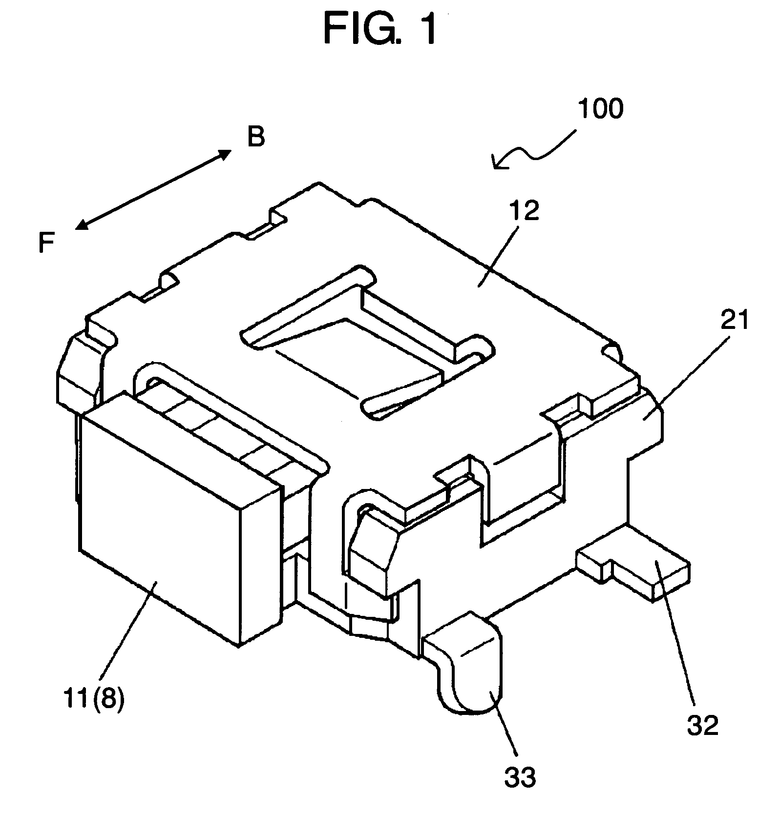
[0043]An exemplary embodiment of the present invention is described with reference to FIG. 1 to FIG. 6.

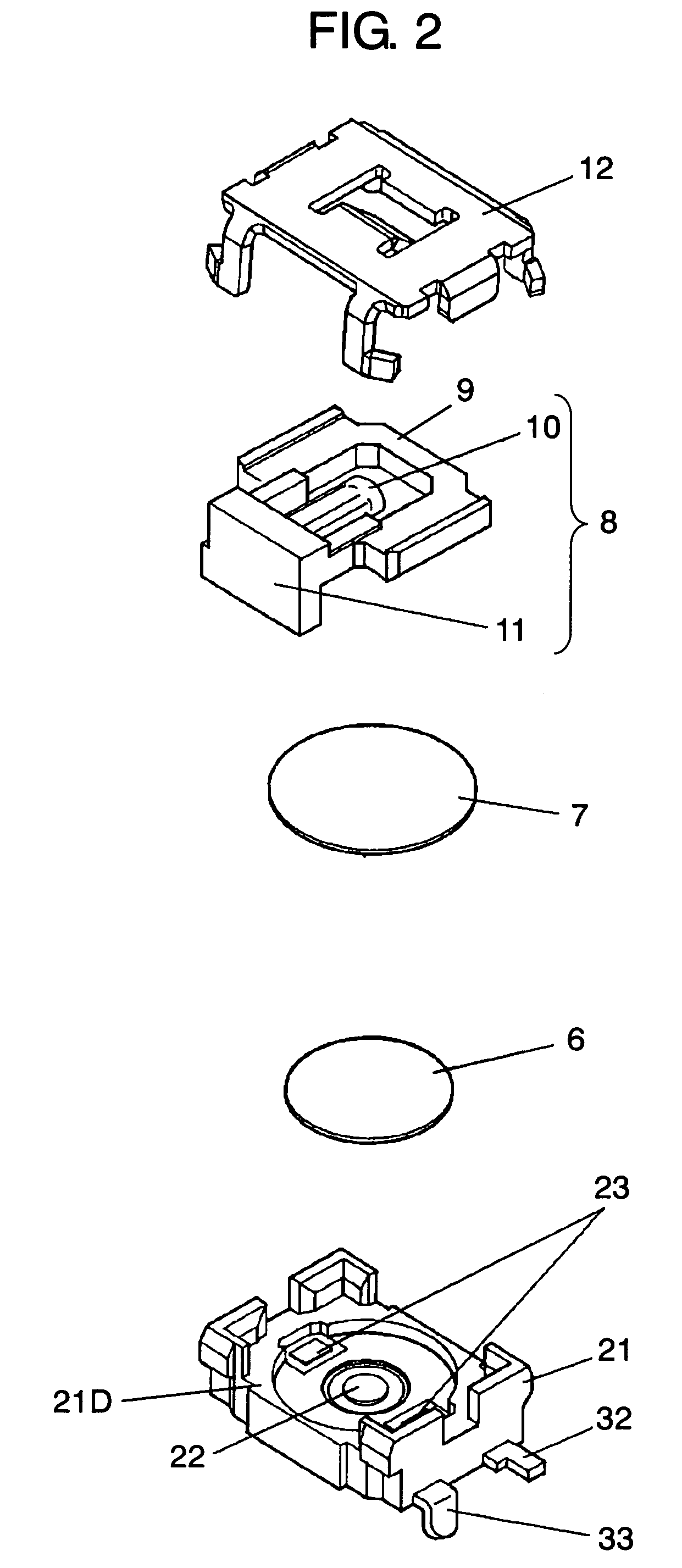
[0044]Push-on switch 100 of the exemplary embodiment has a substantially rectangular plane shape and has insulating-resin-made case 21 having an upwardly opening recessed shape. Center contact 22 and outside contacts 23 are fixed onto the bottom face of the recessed part of case 21. Movable contact 6 having a circular dome shape positioned by the inner wall of the recessed part of case 21 is stored on outside contacts 23.

[0045]The lower surface of the center top of stored movable contact 6 is faced to center contact 22 at a predetermined distance. Flexible insulating sheet 7 h...


PUM


Abstract

A push-on switch is pushed horizontally to the surface of a printed wiring board used in various electronic apparatuses. The push-on switch is of a surface mounted type, in which only front terminals lead from case can be extended vertically downwardly and soldered to the inside of through holes in land parts having the through hole of printed wiring board. Front terminals work as a maintaining means for maintaining a stable mounted state to improve proof strength against an operating force horizontal to the printed wiring board surface. Therefore, the stable mounted state to the printed wiring board is kept also when horizontal pushing is repeated.

Description

BACKGROUND OF THE INVENTION[0001]1. Field of the Invention[0002]The present invention relates to a push-on switch that is operated by being pushed horizontally to a printed wiring board surface used for various electronic apparatuses.[0003]2. Background Art[0004]Recently, for operating an electronic apparatus, a method of performing a predetermined operation using an operating unit formed of arranged push-on switches has become widespread.[0005]Various operation methods of push-on switches have been required with widespread use of various apparatuses. The demand for a push-on switch to be pushed horizontally to a printed wiring board surface increases. Small and light apparatuses are manufactured, so that especially surface-mounted-type push-on switches are preferred.[0006]Japanese Patent Unexamined Publication No. H5-1126 discloses a conventional push-on switch that is operated by being pushed horizontally to a printed wiring board surface.[0007]The conventional push-on switch is d...

Claims


Application Information

Patent Timeline
Patent Type & Authority Patents(United States)
IPC IPC(8): H01H5/18H01H3/42H01H13/52H01H1/58H01H9/02H01H13/04H01H13/48H01H15/10
CPCH01H1/5805H01H13/48H01H2001/5888H01H15/102
Inventor WATANABE, HISASHITAMANO, KOJI
Owner PANASONIC CORP
Why Eureka
Try Eureka