Slow-wave structure for ridge waveguide

a technology of slow wave and ridge waveguide, which is applied in the direction of waveguides, delay lines, electrical equipment, etc., can solve the problems of increased loss, large rectangular waveguide dimensions, and large bulky rectangular waveguides, and achieve the effect of reducing the size of waveguides

Active Publication Date: 2006-04-04
NORTHROP GRUMMAN SYST CORP
View PDF9 Cites 10 Cited by
  • Summary
  • Abstract
  • Description
  • Claims
  • Application Information

AI Technical Summary

Benefits of technology

[0012]The present invention further provides a method of maintaining. a characteristic impedance of and reducing a size of a waveguide operating at a certain frequency. The method comprises the following steps. A top wall portion of the waveguide is processed to form a ridge projecting into the waveguide. The ridge extends along an elongate direction of the waveguide. The ridge is partitioned into a plurality of small ridges arranged in parallel and separated with each other by a gap, so as to effectively introduce a plurality of inductances between the ridge segments. The ridge segments themselves capacitively couple to a bottom wall of the waveguide, such that the ridge segments and the gaps form a transmission line operating in such a way as to slow a wave propagating down the waveguide.

Problems solved by technology

As known in the art, the rectangular waveguide is normally very bulky and costly.
Although the lately developed micro-machine technique seems to resolve the cost issue, the dimension of the rectangular waveguide is still too large to be useful.
As a consequence, the cross-sectional area required for operation at a certain frequency is reduced compared to the rectangular waveguide, but the decreased impedance leads to two deleterious effects, including increased loss (degraded performance) due to the increased current that must flow through the conductive walls, and the limited bandwidth obtainable in coupling structures connecting to the ridge waveguide.
Such E-plane filters, though providing a slow-wave structure, does not resolve the cross-sectional size issue of the rectangular waveguides, and do not take advantage of the increased impedance.
Further, the characteristic impedance of such a waveguide filter will not be reduced because of size reduction.

Method used


Image

  • Slow-wave structure for ridge waveguide
  • Slow-wave structure for ridge waveguide
  • Slow-wave structure for ridge waveguide

Examples


Embodiment Construction

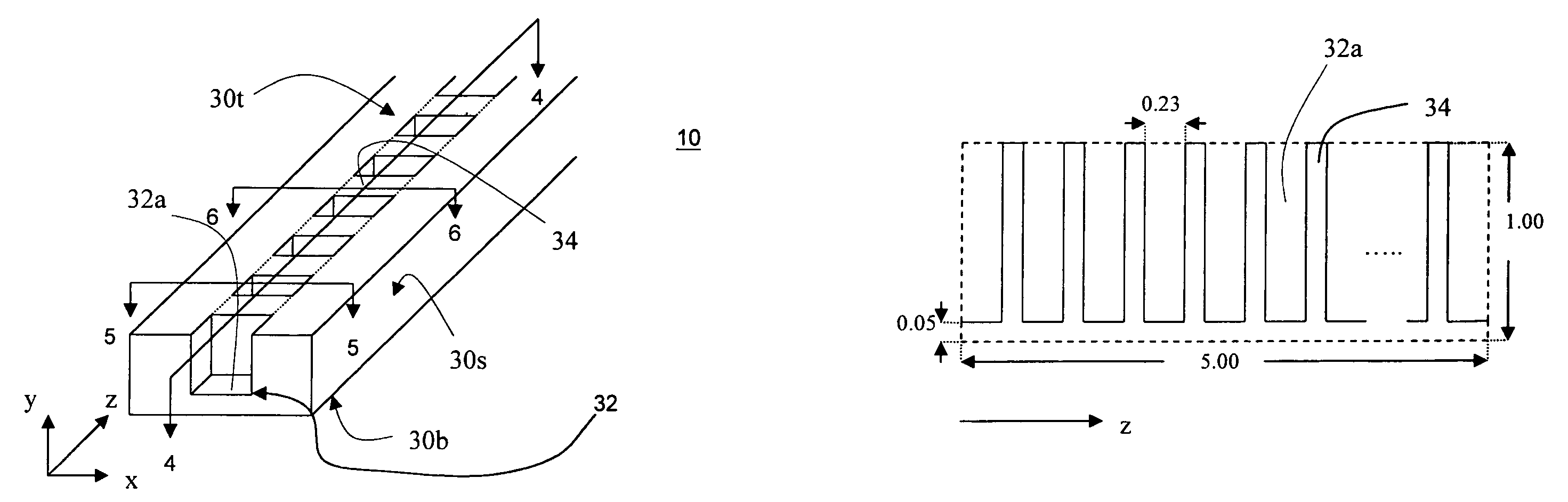
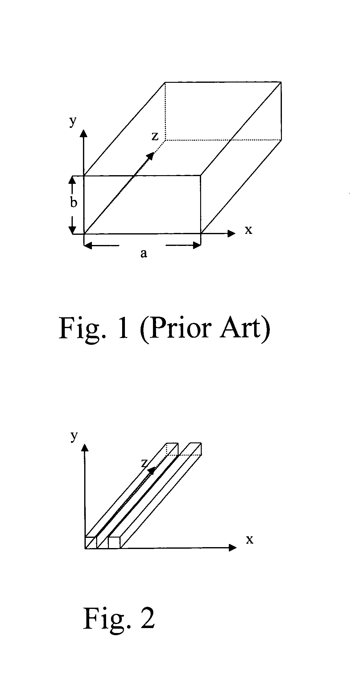
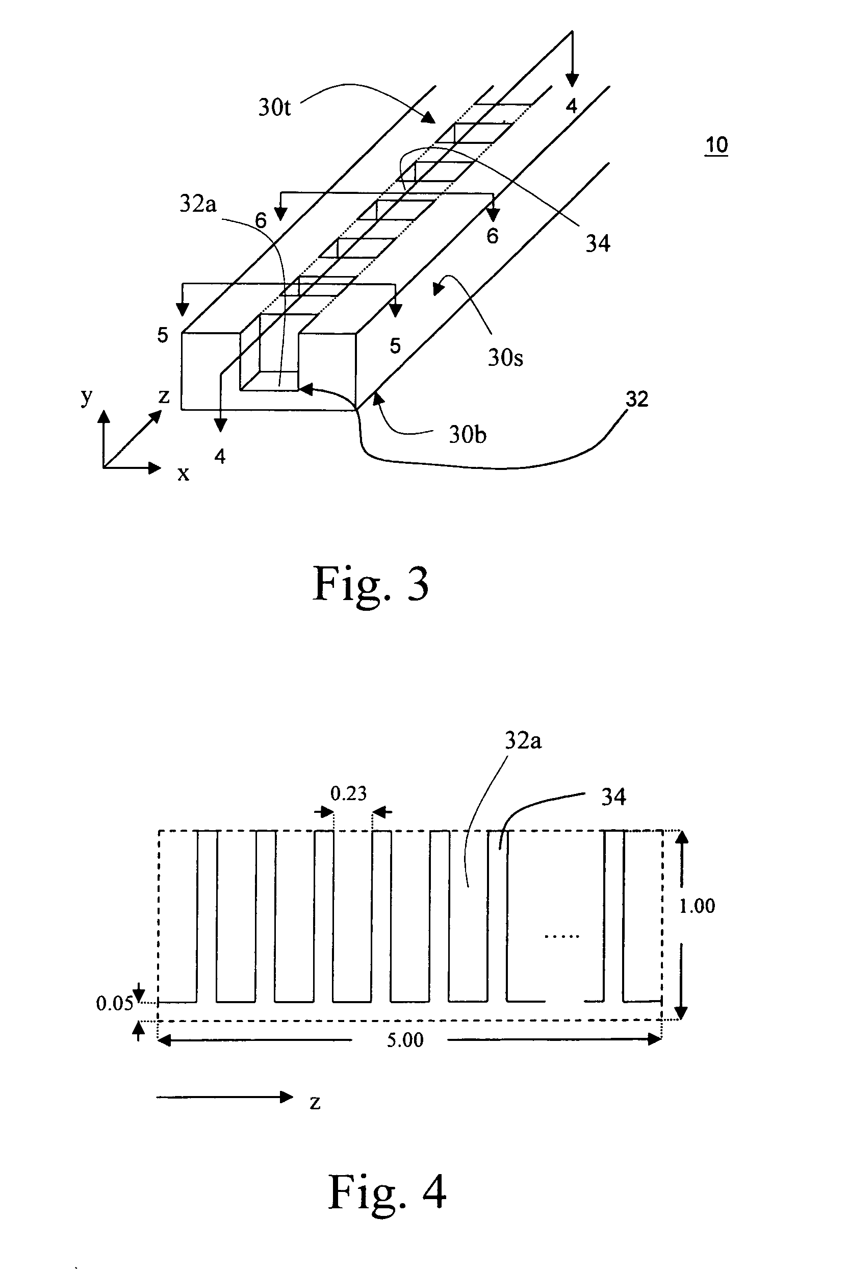
[0022]As mentioned above, ridge waveguides have been proposed as a useful modification to resolve the size issue of the rectangular waveguides. To further resolve the reduced characteristic impedance problem of the ridge waveguide and to adequately reduce the phase velocity of the wave propagated within the ridge waveguide, the present invention provides a ridge waveguide having a slow-wave structure 10 as shown in FIG. 3. The ridge waveguide has a hollow rectangular tube with a top wall 30t, two opposing side walls 30s and a bottom wall 30b. Preferably, the top, side and bottom walls 30t, 30s and 30b are fabricated from conductive or metallic materials, and the tube is filled with air. According to IRE standards, the coordination system as shown in FIG. 4 includes an x direction taken as the longer transverse dimension, a y direction taken as the shorter transverse dimension, and a z direction taken as the longitudinal dimension, along which the wave propagates within the ridge wav...


PUM

PropertyMeasurementUnit
heightaaaaaaaaaa
heightaaaaaaaaaa
widthaaaaaaaaaa

Abstract

A ridge waveguide filter having a slow-wave structure. The ridge waveguide has an elongate hollow tube formed of a conductive sidewall. At least a first part of the conductive sidewall periodically is recessed along an elongate direction of the hollow tube, such that a plurality of ridges is formed to project in the hollow tube. The sidewall is fabricated from metallic materials. The hollow tube includes a rectangular hollow tube or a circular hollow tube, for example. The ridges are equally spaced from and parallel with each other. Each of the ridges has a bottom surface parallel with a second part of the conductive sidewall. The second part of the conductive sidewall is opposite to the first part of the conductive sidewall.

Description

STATEMENT RE: FEDERALLY SPONSORED RESEARCH / DEVELOPMENT[0001]Not ApplicableCROSS-REFERENCE TO RELATED APPLICATIONS[0002]Not ApplicableBACKGROUND OF THE INVENTION[0003]The present invention relates in general to a waveguide filter, and more particularly, to a ridge waveguide filter having a slow-wave structure.[0004]Waveguide filters have been widely known to provide outstanding performance at microwave frequencies compared to other technologies such as microstrips, striplines or even coax transmission lines. Depending on the configurations and dimensions, low-pass, high-pass, and band-pass waveguide filters have been developed to separate the various frequency components of a complex wave. FIG. 1 shows a conventional rectangular waveguide. The rectangular waveguide is typically a hollow metallic tube with a rectangular cross-section. According to IRE standards, the coordinate system as shown in FIG. 1 includes the x direction taken as the longer transverse dimension, the y direction ...

Claims


Application Information

Patent Timeline
Patent Type & Authority Patents(United States)
IPC IPC(8): H01P1/207H01P9/00
CPCH01P1/207H01P9/00Y10T29/49016Y10T29/49002Y10T29/49117
Inventor PETERSON, KENT E.NACILLA, DELFIN Q.BARNER, JEFFREY B.
Owner NORTHROP GRUMMAN SYST CORP
Why Eureka
Try Eureka