Module retention latch assembly

a module and latch technology, applied in the field of adapter modules, can solve the problems of difficult operation of thumb screws in environments with many cables, complex structure, and many parts of adapter modules, and achieve the effect of easy sliding

Inactive Publication Date: 2006-04-04
MOLEX INC
View PDF30 Cites 24 Cited by
  • Summary
  • Abstract
  • Description
  • Claims
  • Application Information

AI Technical Summary

Benefits of technology

[0009]It is therefore a general object of the present invention to provide an adapter module that easily slides into a an adapter frame and which uses a moveable latch to retain it in place within the frame.
[0010]Another object of the present invention is to provide an adapter module that utilizes a simple wire bail latch having two free ends that engage openings in the frame, and the bail latch is moveable about its free ends between two positions, wherein in one of the two positions, the free ends of the bail latch extend outwardly from the adapter module to provide interfering posts that serve to retain the adapter module in place within the adapter / frame and in the other of the two positions, the free ends of the bail latch are withdrawn inwardly into the adapter module so that they do not interferingly engage the adapter frame to thereby permit the adapter module to be easily removed from the bezel.
[0011]A further object of the present invention is to provide an adapter module with a retention bail latch that is moveable between two positions wherein the adapter module is either retained within a guiderail or removable therefrom, the bail latch preventing the cable assembly from being attached to the transceiver within the adapter module prior to installation of the adapter module into its host unit.
[0021]The housing may be formed from a single piece of sheet metal, thereby reducing the cost involved with the structure as compared to a conventional die-cast module housing. In the forming process, a blank is stamped and formed to define an end wall of the module housing with a module entrance that is flanked by two slots. The bail latch has a central bail portion that is manipulated by the user and which serves as a blocking element that crosses the entrance of the housing in the second position. It preferably has two legs that extend from the central portion at angles thereto to define a general U-shape and each leg diverges at an angle to terminate in a free end that is spaced apart from the central portion in two different planes. A cam member is formed in the housing that projects into one of the two slots. This cam member presents a surface that the bail latch leg encounters in its movement between the first and second operative positions. In one of the two positions, the bail latch leg contacts the cam member and only the free end of the bail latch that extends from that particular leg is moved inwardly of the housing and out of engagement with an exterior assembly or housing so that the module assembly may be removed therefrom.

Problems solved by technology

These thumbscrews are difficult to operate in environments with many cables, for the user has to move the cables to the side when installing, removing or reconfiguring the cables.
Thus, these adapter modules are not easily pluggable.
This structure is complex and uses many parts, so that alignment is a concern when assembling the mechanism.
Other retention devices require portions of the mechanism, such as the cams, to be formed as part of the module housing and thus increase the cost of manufacture of the module housing.
These die cast housings may not be utilized in certain module applications.
Additionally, many module retention systems have no means integrated with them that indicate the status of the module in either a latched or unlatched condition upon actuation of the retention mechanism.

Method used


Image

  • Module retention latch assembly
  • Module retention latch assembly
  • Module retention latch assembly

Examples


embodiment 200

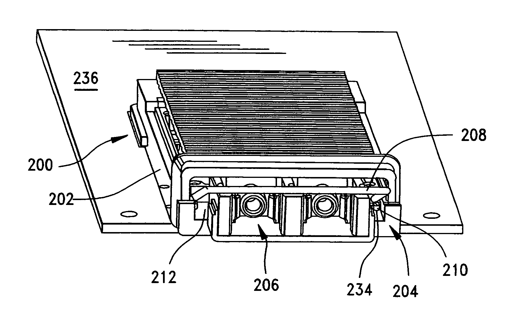
[0071]Another embodiment 200 is illustrated in FIGS. 10–11 where the module 30 includes a bail latch 141 that has a recess or slot 146 formed therein to receive a cable or patch cord.

[0072]FIGS. 13–19 illustrate the interaction of the bail latch free ends and the module adapter frame more clearly. In FIG. 13, the assembly 200 is shown as an adapter frame 202 that has a pair of side walls which are interconnected by rear and front members. The adapter frame 202 is shown mounted to a circuit board 236 and the frame holds an electronic module 204 therein. The module shown is an optical transceiver, but it will be understood that other suitable types of components may be used as modules.

[0073]The module 204 has a pair of openings 206 that communicate with its front face to permit the coupling thereto of cables and the like. The module 204 is equipped with a moveable bail latch 208 of the type described previously. The bail latch 208 has a U-shape with a base 214 that may by moved up or ...

embodiment 500

[0076]FIGS. 20–32 illustrate another, “single-ended” embodiment 500 of the invention where one end of the bail latch is fixed for rotation only in the housing, while the other end of the bail latch is free to rotate and to translate (i.e., move laterally) in and out of engagement with an outer assembly or shell. In this embodiment, the module assembly can be seen to include a circuit board 501 and a frontal housing 502 that is attached to the circuit board 501 by way of a suitable means, such as mounting screws 504 that extend through a circuit board 501 and holes 600 formed in mounting tabs 520. A bail latch 550 is provided for opening and blocking access to the interior opening 560 of the housing 502. As illustrated best in FIGS. 20–21, the overall module assembly can be seen to include an elongated circuit board 501 having a rear insertion edge 512 with a plurality of conductive pads or traces 513 disposed thereon for engagement with opposing contacts of an edge connector (not sh...


PUM


Abstract

A housing for an adapter module is provided with a bail latch mechanism that serves to engage and disengage the frame into which the adapter module housing fits. The housing is stamped and formed from a piece of sheet metal and the bail latch is rotatably mounted in the housing. The bail latch is movable between two positions and the bail latch engages a cam member that is stamped and formed in one side of the housing so that movement of one end of the bail latch over the cam member cams one of the two free ends of the bail latch inwardly into the housing to thereby release the housing from the adapter frame.

Description

REFERENCE TO RELATED APPLICATIONS[0001]This application claims priority from U.S. Provisional Patent Application No. 60 / 512,630, filed Oct. 20, 2003.BACKGROUND OF THE INVENTION[0002]The present invention relates generally to adapter modules, and more particularly to an adapter module having a retention member that is easily operable to hold the adapter module in place or to release it from within an adapter frame.[0003]Adapter frames or modules are used in many different applications and are usually used to contain an electrical component, such as an optical transceiver or a cable to board connector. Adapter modules are used in a wide variety of applications that range from simple connecting faces between hard (copper) conductor wiring to more sophisticated applications that may involve optical fibers, flexible or printed cables, etc. In many instances, adapter modules house converters that are used to convert optical signals or electrical signals or electrical signals to optical si...

Claims


Application Information

Patent Timeline
Patent Type & Authority Patents(United States)
IPC IPC(8): H05K7/16H01R13/62H05K5/06H05K7/18H01R12/16G02B6/42H01R13/00H05K5/00H05K7/00H05K7/14
CPCG02B6/4201G02B6/4292G02B6/4246G02B6/4261G02B6/428G02B6/4284
Inventor PELOZA, KIRK B.
Owner MOLEX INC
Why Eureka
Try Eureka