Method for expediting a short message via a server when a communication participant of a communication network is not available

a technology of communication network and server, applied in the field of emitting signals, can solve problems such as disruptive experiences and especially unfavorable situations

Inactive Publication Date: 2006-04-04
NOKIA SIEMENS NETWORKS GMBH & CO KG
View PDF10 Cites 19 Cited by
  • Summary
  • Abstract
  • Description
  • Claims
  • Application Information

AI Technical Summary

Benefits of technology

[0008]The invention has one advantage that adequate information about the respective calling subscriber station can be provided in a relatively simple manner at a required station of the communication network by the short message transmitted thereto. This includes at least the subscriber number of the respective calling subscriber station, without having to be subject to the disadvantage set out above of disruption due to the emission of acoustic report signals, as occur with conventional call signal redirection.
[0016]The subscriber number of a calling subscriber station is advantageously included in the short message transmitted to the mentioned defined station in the course of the established information service to set up a link from the station receiving this short message, in particular a mobile radio subscriber station, to the respective calling subscriber station. This function, known as the click-to-dial function, allows a link to be established in an especially user-friendly manner between the mentioned station and the respective subscriber station that called originally.

Problems solved by technology

This is sometimes experienced as disruptive, especially when the communication participant mentioned is available by mobile radio in the communication network.
This situation is also experienced as especially unfavorable, when the respective communication participant is traveling abroad with their mobile radio device.

Method used


Image

  • Method for expediting a short message via a server when a communication participant of a communication network is not available
  • Method for expediting a short message via a server when a communication participant of a communication network is not available

Examples


Embodiment Construction

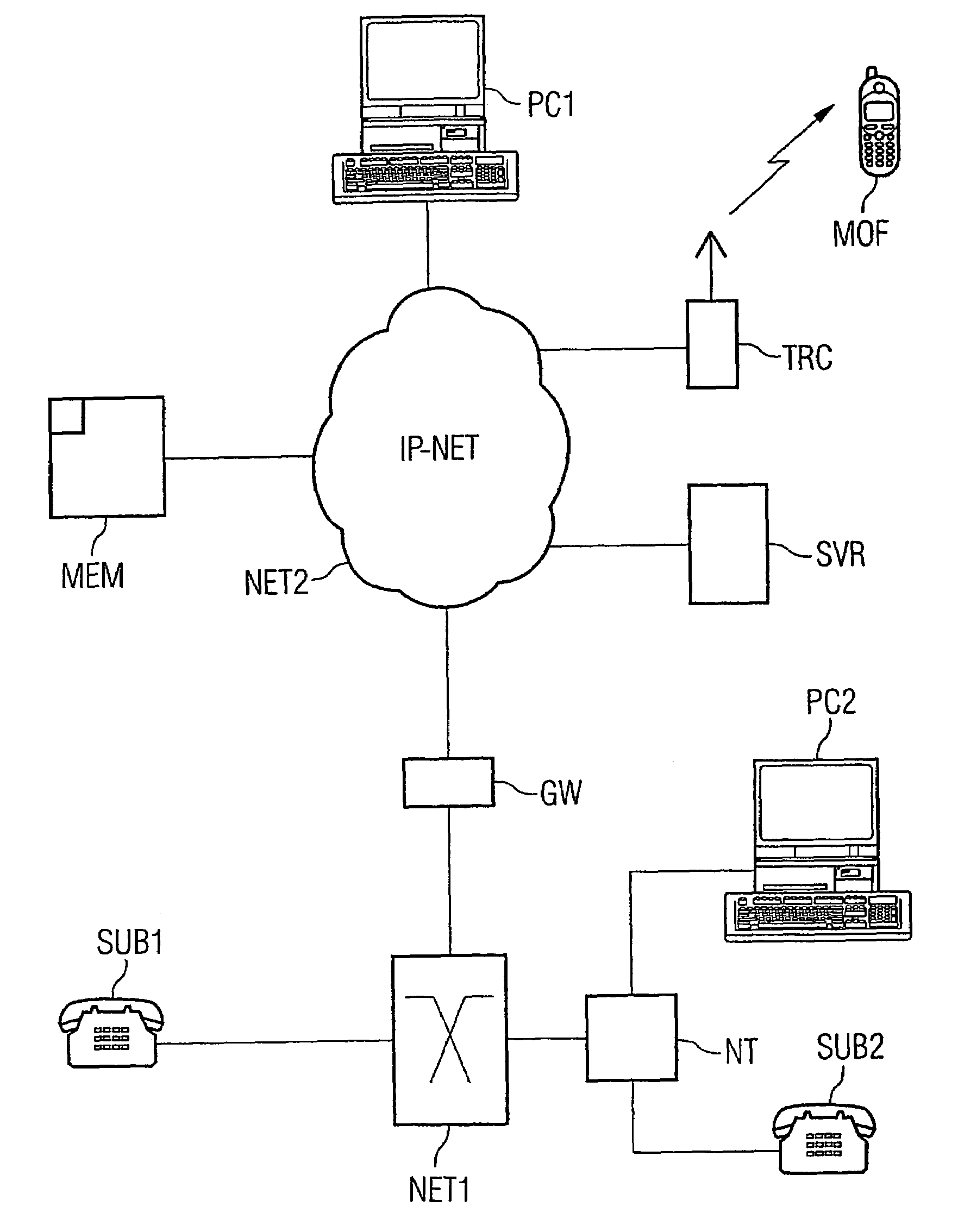
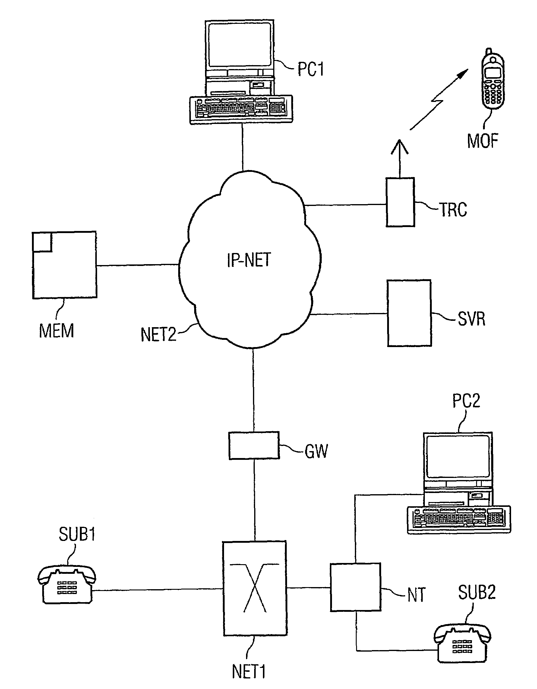
[0019]FIG. 1 shows a communication network, with which two subnetworks NET1 and NET2 are associated. The one subnetwork NET1 is provided by a network that can, for example, be a fixed network, such as the commercially available switching system EWSD. The respective network NET1 can, however, also be an IP network, i.e. an internet protocol based network. The other, second network NET2 is provided by an internet protocol based network IP-NET that is linked to the first-mentioned subnetwork NET1 via at least one transition device (gateway) GW. The second subnetwork NET2 can, for example, be the currently available internet.

[0020]Linked to the network NET1 representing the first subnetwork of the communication network are a plurality of subscriber stations of which two subscriber stations SUB1 and SUB2 are shown in FIG. 1. The subscriber station SUB1 can, for example, be an analog subscriber station and the subscriber station SUB2 can, for example, be an ISDN subscriber station that is...


PUM


Abstract

The invention relates to a method for emitting signal when a communication participant is not available on a subscriber station (SUB2) of a first partial network (NET1), especially a fixed network, associated with a communication network, once a call has arrived that was destined for the respective subscriber station, to a defined station of a second partial network (NET2), especially Internet, associated with the mentioned communication network which is linked with the first partial network (NET1) via at least one transition device (GW), and wherein communication links from and to a mobile radio device (MOF) associated with the respective communication participant can be established as radio links. According to the invention, a short message signal is transmitted to the defined station of the respective second partial network (NET2), via call redirection from the mentioned subscriber station (SUB2) to a server (SVR) associated with the second partial network (NET2) and by means of an information service defined in said server (SVR), said message comprising at least the subscriber number of the calling subscriber station (SUB1).

Description

CLAIM FOR PRIORITY[0001]This application claims priority to International Application No. PCT / EP02 / 09145, which was published in the German language on Mar. 6, 2003, which claims the benefit of priority to Germany Application No. EP 01120255.3 which was filed in the German language on Aug. 23, 2001.TECHNICAL FIELD OF THE INVENTION[0002]The invention relates to a method for emitting a signal when a communication participant is not availableBACKGROUND OF THE INVENTION[0003]Generally, when a communication participant is not available at a subscriber station of a communication network of the type considered above, a signal is emitted to any other switching center of the respective communication network, at which the respective communication participant is henceforth available. This known method, also referred to as call signal redirection, means that all calls that have not been accepted at the first mentioned switching center of the respective communication network are directed to the ...

Claims


Application Information

Patent Timeline
Patent Type & Authority Patents(United States)
IPC IPC(8): H04Q7/20H04M3/42H04M3/53H04M7/00H04W4/12H04W4/16
CPCH04M3/42H04W4/12H04M7/003H04M3/5322H04W4/16H04M2203/052
Inventor KNAEBCHEN, ANDREASPETERSEN, VOLKER
Owner NOKIA SIEMENS NETWORKS GMBH & CO KG
Why Eureka
Try Eureka