Pedal structure for a bicycle

a pedal structure and bicycle technology, applied in the direction of mechanical control devices, process and machine control, instruments, etc., can solve the problems of inconvenient user assembly and disassembly, and achieve the effect of reducing the disadvantage of the conventional pedal structure and / or obviating the disadvantag

Inactive Publication Date: 2006-04-11
HSIAO CHIN HE +1
View PDF7 Cites 20 Cited by
  • Summary
  • Abstract
  • Description
  • Claims
  • Application Information

AI Technical Summary

Benefits of technology

[0006]The present invention is to mitigate and / or obviate the disadvantage of the conventional pedal structures for a bicycle.
[0007]The primary objective of the present invention is to provide a pedal structure for a bicycle, wherein the front binding plate and the rear binding plate provide an inward directed clamping force and form an elastic receiving space for clamping the cleat in an elastic manner, so that the cleat can be mounted on and detached from the pedal body easily and conveniently, thereby facilitating assembly and disassembly of the shoe.
[0008]Another objective of the present invention is to provide a pedal structure for a bicycle, wherein the cleat can be clamped on the pedal body rigidly and stably by the elastic clamping force of the front binding plate and the rear binding plate.
[0009]A further objective of the present invention is to provide a pedal structure for a bicycle, wherein the clamping force applied on the cleat is evenly distributed by the front binding plate and the rear binding plate, so that the cleat can be mounted on and detached from the pedal body easily and conveniently, thereby saving the manual energy.
[0010]A further objective of the present invention is to provide a pedal structure for a bicycle, wherein the front binding plate and the rear binding plate co-operate to provide a larger clamping force, so that the cleat can be clamped on the pedal body rigidly and stably.
[0011]A further objective of the present invention is to provide a pedal structure for a bicycle, wherein the distance between the pivot ear and the clamping portion of the front binding plate is shorter than that between the pivot ear and the concave portion of the rear binding plate, so that the torque required for rotating the front binding plate is greater than that required for rotating the rear binding plate. Thus, the front end of the cleat is initially inserted into the front binding plate without having to provide a torque, and the rear end of the cleat is then snapped into the rear binding plate by applying a smaller torque, thereby facilitating operation of the user, saving the manual energy, and satisfying the ergonomic design.

Problems solved by technology

In addition, it is difficult to place the cleat between the front binding plate 73 and the rear binding plate 74, thereby causing inconvenience to the user in assembly and disassembly.

Method used


Image

  • Pedal structure for a bicycle
  • Pedal structure for a bicycle
  • Pedal structure for a bicycle

Examples


Embodiment Construction

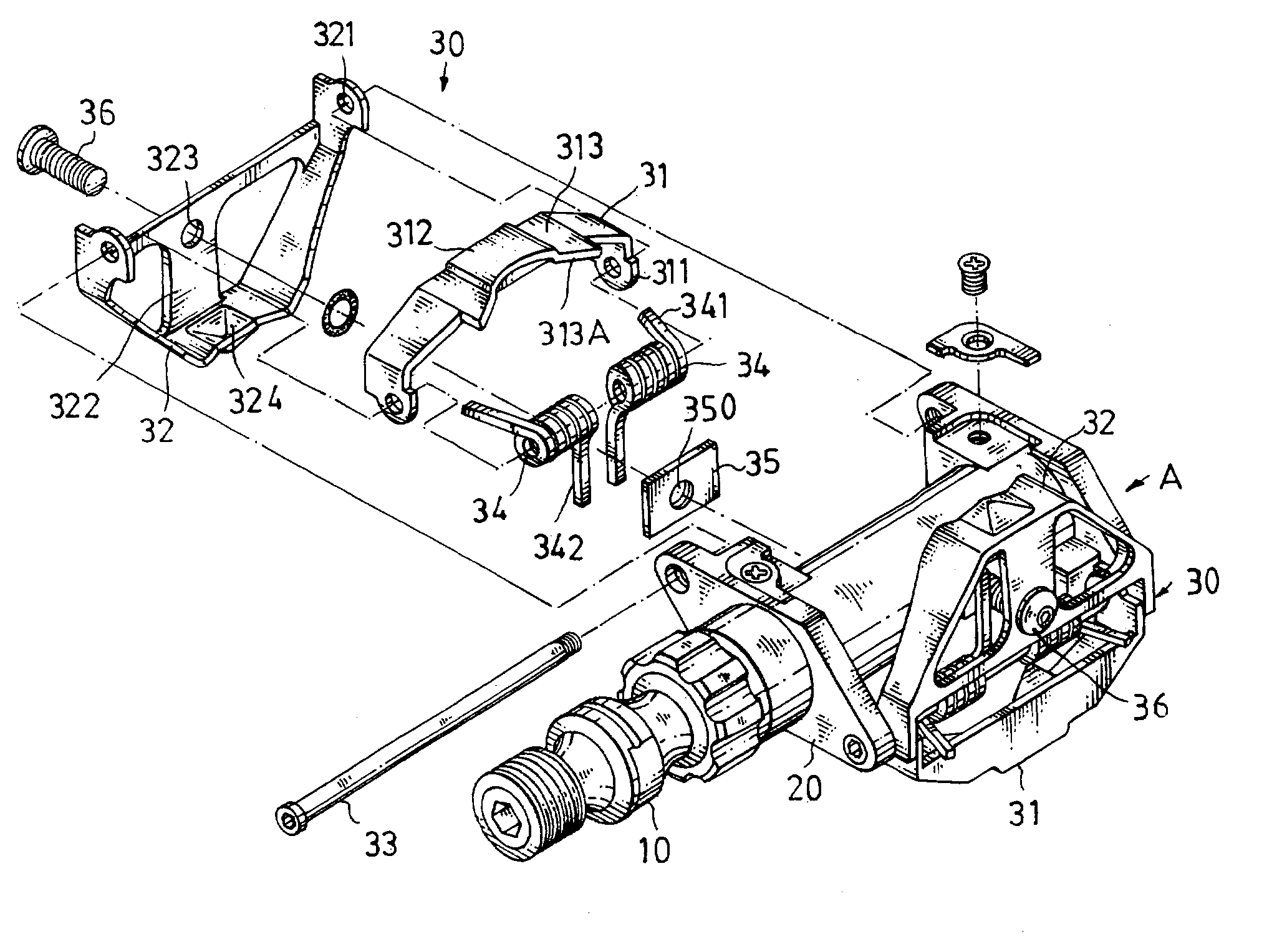
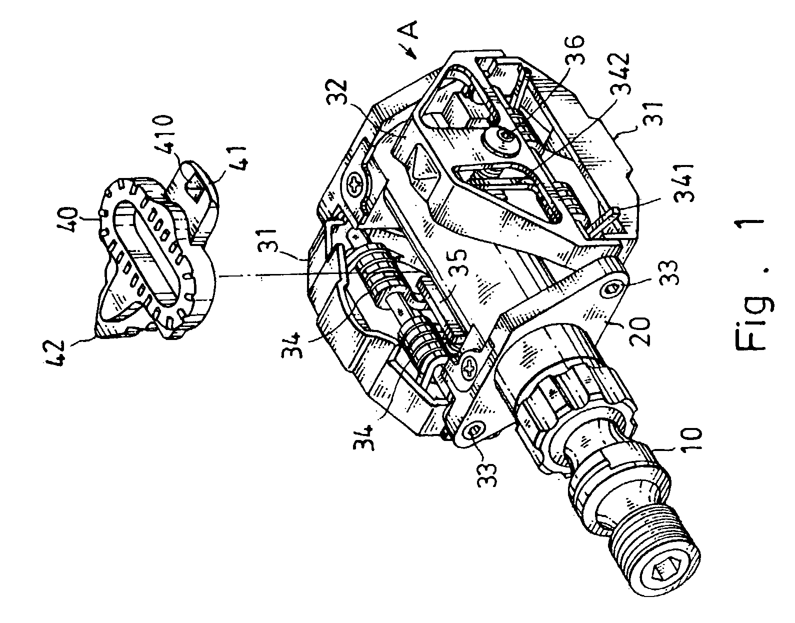
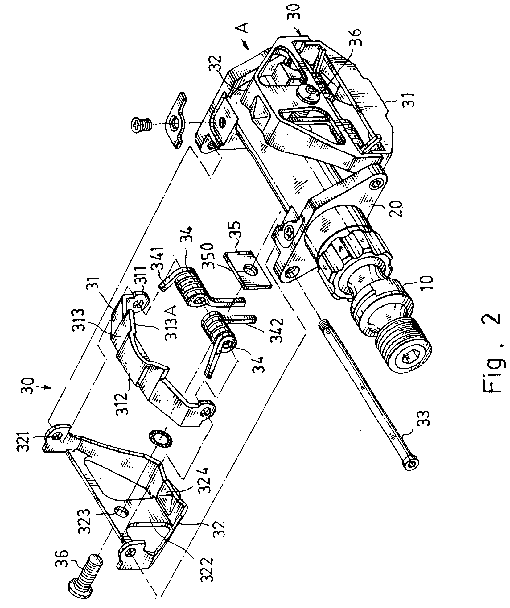
[0036]Referring to the drawings and initially to FIGS. 1–6, a pedal structure “A” for a bicycle in accordance with the preferred embodiment of the present invention comprises a pedal body 20, and an elastic clamping device 30.

[0037]The pedal body 20 has two opposite sides and is provided with a spindle 10.

[0038]The elastic clamping device 30 is mounted on each of the two opposite sides of the pedal body 20, and includes a front binding plate 31, a rear binding plate 32, a pivot shaft 33, two torsion springs 34, an urging plate 35, and an adjusting bolt 36.

[0039]In assembly, two elastic clamping devices 30 are each mounted on a respective one of the two opposite sides of the pedal body 20, wherein the front binding plate 31 and the rear binding plate 32 of one of the two elastic clamping devices 30 face the rear binding plate 32 and the front binding plate 31 and of the other of the two elastic clamping devices 30 respectively.

[0040]The pivot shaft 33 of the elastic clamping device 3...


PUM


Abstract

A pedal structure for a bicycle includes a pedal body, and an elastic clamping device. The elastic clamping device is mounted on each of the two opposite sides of the pedal body and includes a front binding plate, a rear binding plate, a pivot shaft, at least one torsion spring, an urging plate, and an adjusting bolt. Thus, the cleat can be mounted on and detached from the pedal body easily and conveniently, and can be clamped on the pedal body rigidly and stably by the elastic clamping force of the front binding plate and the rear binding plate.

Description

BACKGROUND OF THE INVENTION[0001]1. Field of the Invention[0002]The present invention relates to a pedal structure for a bicycle, and more particularly to a pedal structure for a bicycle, wherein the cleat can be mounted on and detached from the pedal body easily and conveniently, and can be clamped on the pedal body rigidly and stably by the elastic clamping force of the front binding plate and the rear binding plate.[0003]2. Description of the Related Art[0004]A first conventional pedal structure for a bicycle in accordance with the prior art shown in FIG. 11 comprises a pedal body 70, and a clamping device 72. The pedal body 70 is provided with a spindle 71. The clamping device 72 is mounted on the pedal body 70, and includes a front binding plate 73, a rear binding plate 74, a torsion spring 75, and an adjusting bolt 76. A cleat (not shown) is secured on the bottom of a special shoe (not shown) which is used for the racing sportsman. In assembly, the cleat is mounted on the peda...

Claims


Application Information

Patent Timeline
Patent Type & Authority Patents(United States)
IPC IPC(8): B62M3/00G05G1/30B62M3/08
CPCB62M3/086Y10T74/217Y10T74/2168
Inventor HSIAO, CHIN-HEXIE, CHIN-LONG
Owner HSIAO CHIN HE
Why Eureka
Try Eureka