Air bleed-off valve

a technology of air bleed-off valve and valve body, which is applied in the direction of mechanical equipment, functional valve types, transportation and packaging, etc., can solve the problems of reducing the effect of the jet and damage to the heater, and achieve the effect of reducing the cavitation of the pump

Inactive Publication Date: 2006-04-11
ELNAR JOSEPH G
View PDF15 Cites 7 Cited by
  • Summary
  • Abstract
  • Description
  • Claims
  • Application Information

AI Technical Summary

Benefits of technology

[0006]The present invention addresses the above and other needs by providing an automatic air bleed valve which allows air to escape from water lines. Allowing air to thus escape, eliminates pump cavitation and / or air in the heater, and the automatic air bleed valve allows air to escape even if the pump is not running. The air bleed valve is positioned between a pump and the heater, and is higher than the heater, and no higher than the water level in the spa. The air bleed valve comprises a vertically disposed cylinder containing a piston and having a valve bottom, a valve inlet proximal to the valve bottom, a valve top, and a valve outlet proximal to the valve top. The piston moves vertically in the cylinder. While water flow is present in the spa piping system, the piston raises and cooperates with a seal to prevent a flow of water through the valve. While there is no water flow in the spa piping system, the piston drops and allows the air to flow past the piston to the valve outlet.

Problems solved by technology

If sufficient air enters the pump, and is pumped through the heater, overheating and damage to the heater may result.
Unfortunately, the float and valve arrangement requires at least twenty five pounds of back pressure to properly function, and creating artificial back pressure in a spa would reduce the effect of the jets.
The gas is removed by routing pipe to a vent above the pump, however, the '167 patent does not describe a valve or cooperation of a valve with a heater and does not suggest that the vent will remove air from a pump and heater combination in a spa.

Method used


Image

  • Air bleed-off valve
  • Air bleed-off valve
  • Air bleed-off valve

Examples


Embodiment Construction

[0024]The following description is of the best mode presently contemplated for carrying out the invention. This description is not to be taken in a limiting sense, but is made merely for the purpose of describing one or more preferred embodiments of the invention. The scope of the invention should be determined with reference to the claims.

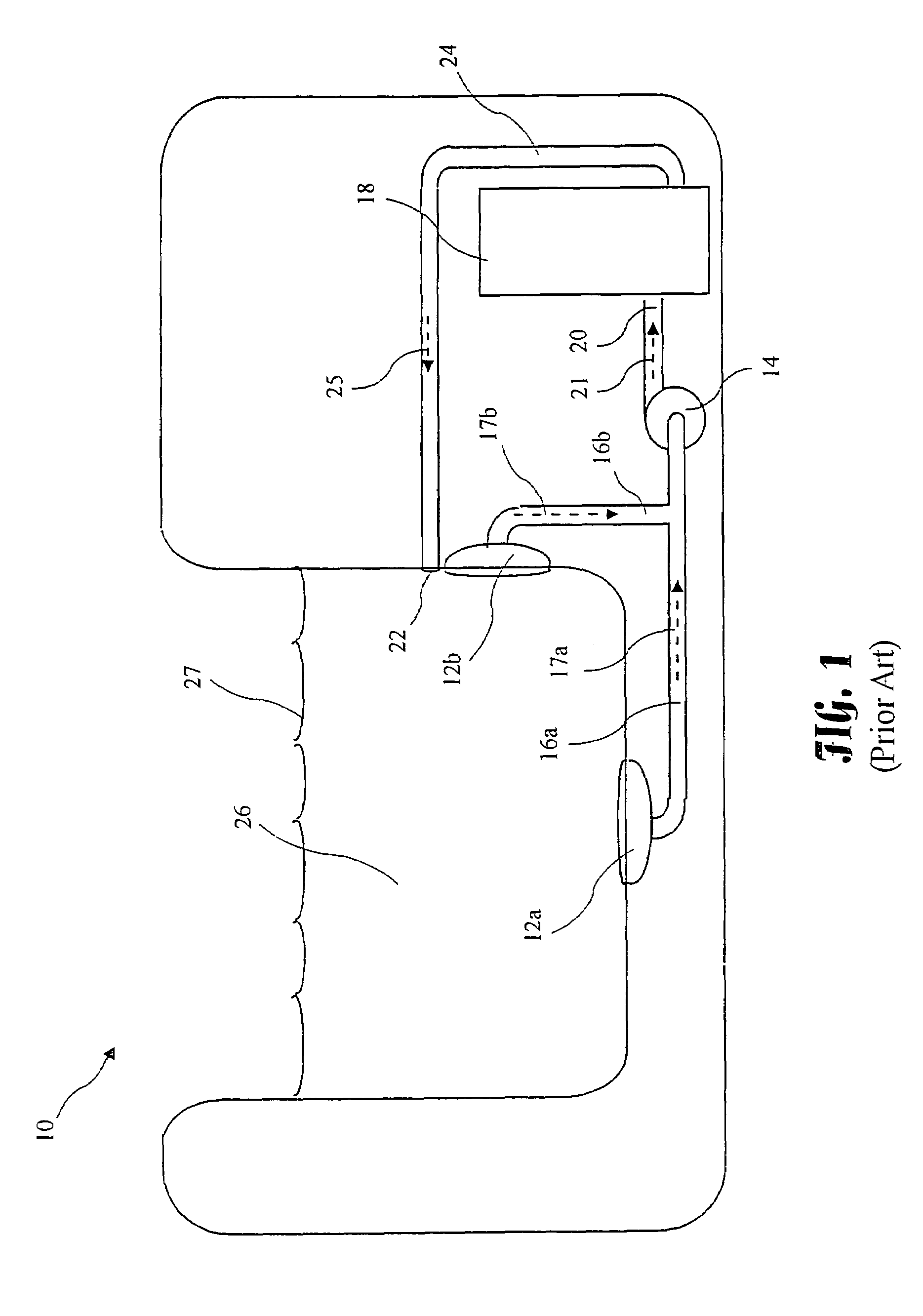
[0025]A prior art spa 10 is shown in FIG. 1. The spa 10 includes drains 12a and 12b. The drains 12a, 12b are in fluid communication with a pump 14 through first lines 16a and 16b respectively carrying flows 17a and 17b respectively. A heater 18 is in fluid communication with the pump 14 through second line 20 carrying second flow 21. The heater 18 is in fluid communication with at least one jet 22 through line 24 carrying a third flow 25. Water 26 is thereby circulated and heated. If air enters either drain 12a or 12b, and is pumped into the heater 18, damage to the heater 18 may result.

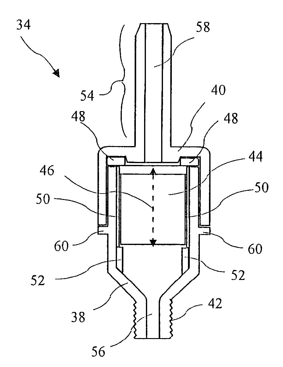
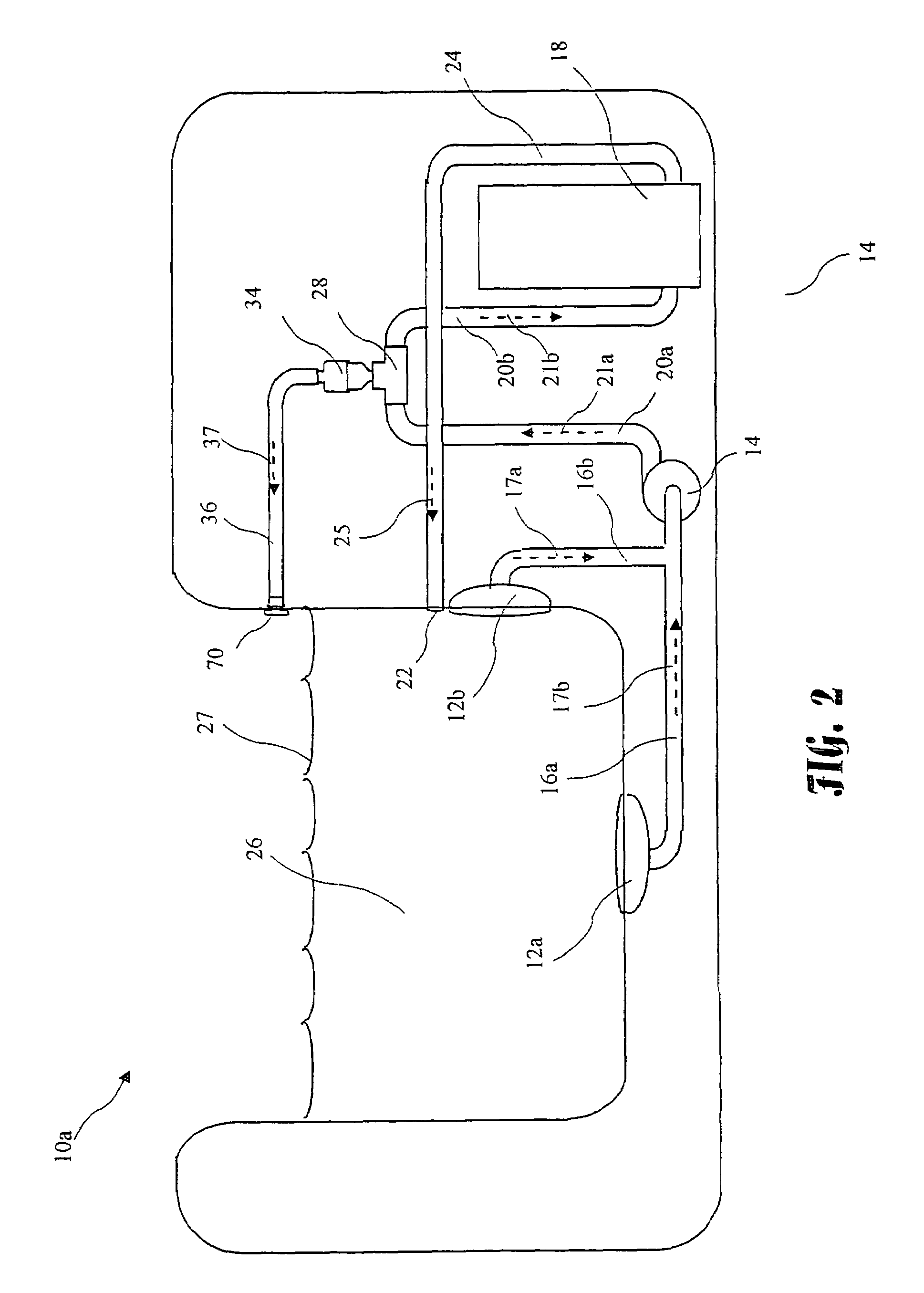
[0026]An improved spa 10a is shown in FIG. 2 including an aut...


PUM


Abstract

An automatic air bleed valve which allows air to escape from water lines. Allowing air to thus escape, prevents pump cavitation and / or air in the heater. The air bleed valve is positioned between a pump and the heater, and is higher than the heater, and no higher than the water level in the spa. The air bleed valve comprises a vertically disposed cylinder containing a piston and having a valve bottom, a valve inlet proximal to the valve bottom, valve top, and a valve outlet proximal to the valve top. The piston moves vertically in the cylinder. While water is present in the cylinder, the piston raises and cooperates with a seal to prevent a flow of water through the valve. While air is present in the cylinder, the piston drops and allows the air to flow past the piston to the valve outlet.

Description

BACKGROUND OF THE INVENTION[0001]The present invention relates to an automatic air bleed-off valve, and more particularly to an air bleed-off valve suitable for use with a spa.[0002]Spas include a pump and heater to provide a flow of heated water to jets as shown in prior art FIG. 1. The pump sucks water through drains and pumps the water through the heater to jets mounted in spa walls. If sufficient air enters the pump, and is pumped through the heater, overheating and damage to the heater may result. Many modern spas include at least two drains as a safety requirement to prevent a user from being held against a drain by pump suction. Because of the additional drains, there is a greater likelihood that one drain will allow air to enter the system and reach the heater. There is thus a need for a valve to automatically bleed off air before the air can reach and damage the heater.[0003]U.S. Pat. No. 3,197,069 issued Jul. 27, 1965 for “System for Dispensing Liquid Having a Meter, an Ai...

Claims


Application Information

Patent Timeline
Patent Type & Authority Patents(United States)
IPC IPC(8): F16K24/04
CPCF16K24/04Y10T137/309
Inventor ELNAR, JOSEPH G.
Owner ELNAR JOSEPH G
Why Eureka
Try Eureka