Device for detecting a deformation of a component

a technology of component and detection device, which is applied in the direction of pedestrian/occupant safety arrangement, instruments, tractors, etc., can solve the problems of high difficulty in reliable detection of accidents or crashes, negative effect of pressure sensor measurement accuracy, and inability to obtain inaccurate measurement results, etc., to achieve the effect of increasing the reliability of such a system

Inactive Publication Date: 2006-04-11
ROBERT BOSCH GMBH
View PDF10 Cites 20 Cited by
  • Summary
  • Abstract
  • Description
  • Claims
  • Application Information

AI Technical Summary

Benefits of technology

[0009]An object of the present invention may include, in general, creating a device for detecting a deformation of a component, which is easily adapted in shape to the corresponding component and is mountable independently of external interference.

Problems solved by technology

With pressure sensors, certain types of interference may make reliable detection of an accident or crash highly difficult.
For example, insufficient sealing in the door structure may cause additional pressure fluctuations which have a negative effect on the measurement accuracy of pressure sensors.
Likewise, in the event of an accident, there may be severe damage to the corresponding vehicle part in which the pressure sensor is installed, and thus inaccurate measurement results may be obtained or there may even be a system failure.
Slamming of a vehicle door or a trunk lid may cause a sudden pressure increase inside the vehicle, so that a faulty signal is delivered for deployment of a vehicle occupant safety application.
In addition, the pressure sensors detect only a limited area, and it is difficult to adapt them to the prevailing geometric design of the corresponding component.

Method used


Image

  • Device for detecting a deformation of a component
  • Device for detecting a deformation of a component
  • Device for detecting a deformation of a component

Examples


Embodiment Construction

[0022]In the figures, the same reference numbers denote the same components or those having the same function.

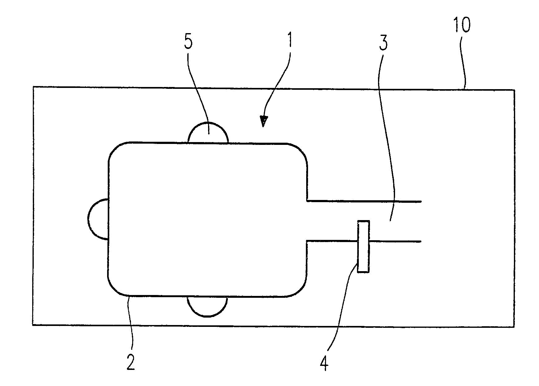
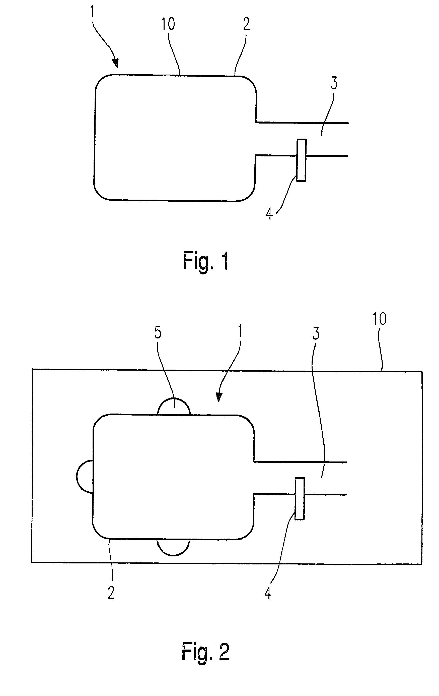
[0023]FIG. 1 illustrates a schematic diagram of a device 1 for detecting a deformation of a component.

[0024]The device 1 is composed of a deformable hollow body arrangement 2 representing any desired component 10 in a motor vehicle, for example, according to the first exemplary embodiment. This may be a two-shell vehicle door or the like.

[0025]According to the first exemplary embodiment, hollow body arrangement 2 has an orifice area 3 in which is mounted a conventional air flow sensor or air velocity sensor 4. Orifice area 3 may be situated in such a way that it is protected from external air flows and its measured data is not influenced by external interfering factors. For example, in the present exemplary embodiment, the orifice area may be provided toward the interior of the vehicle.

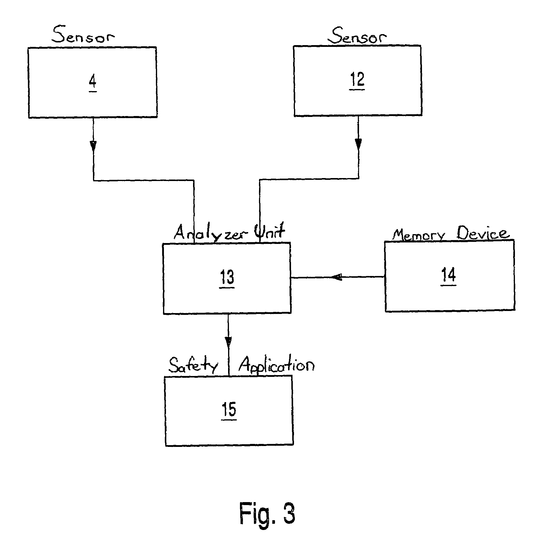
[0026]With sensor 4, it is possible to detect a sudden outflow of air out of compressed co...


PUM


Abstract

A device for detecting a deformation of a component, for example, in the automotive industry, having a deformable hollow body arrangement assigned as a deformation indicator to the component and having at least one orifice area, and at least one sensor device situated in the particular orifice area for measuring an air flow corresponding to the deformation of the hollow body arrangement. In addition, a method of detecting such a deformation of a component and activating an appropriate safety application is described. The measured data is analyzed by an analyzer unit after measurement of the deformation, and a suitable safety application optionally being activated if the measured data of the at least one sensor device indicates a deformation of hollow body arrangement and thus of the component.

Description

FIELD OF THE INVENTION[0001]The present invention relates to a device and method for detecting a deformation of a component.BACKGROUND INFORMATION[0002]Although it is applicable to any desired components, the present invention as well as the problems on which it is based are explained here with respect to an automotive component.[0003]To detect an accident or an impact involving a vehicle, sensors are conventionally installed in the vehicle. By analyzing the measurement results of these sensors, various vehicle occupant safety applications provided in the vehicle may be activated in case of need. Pressure sensors may be used in a part located on the side of the vehicle, e.g., a door of the vehicle for detecting a side impact.[0004]German Patent No. 41 15 202 describes a method and a device for recognizing whether a seat in a vehicle is occupied by a person. A sensor is provided with which a container is filled with an incompressible free-flowing medium. The mass or volume of displac...

Claims


Application Information

Patent Timeline
Patent Type & Authority Patents(United States)
IPC IPC(8): B60K28/10G01M17/007B60R21/01B60R21/16B60R22/46
CPCG01R31/318508B60R21/0136
Inventor FUERTSCH, MATTHIASLORENZ, GERD
Owner ROBERT BOSCH GMBH
Why Eureka
Try Eureka